No products in the cart.
Today we will talk about the correct wiring method of power supply filter capacitors in PCB!
Many engineers like to widen the wiring of the power supply when designing PCB. This is a good method, but if they are not careful, they will ignore the wiring of the capacitor.
please take a look in the image below to figure out the problem

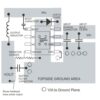
here is some one drew such a circuit under an ideal situation with sufficient space. Because the current will take the shortest path, the current from source to load in the figure below flows approximately along the path of the white line. Smart engineers have already seen the problem. That is to say, if the capacitor is not placed on the path of current, the filtering effect of the capacitor will be greatly reduced. So the first point is that the capacitor should be placed on the path of current flow, or the power supply passes through the capacitor before supplying power to the load.
After understanding the first knowledge point, let’s look at the second circuit

The capacitor wiring below looks beautiful, but in practice this wiring is unreasonable. Some friends may ask, the capacitor is indeed placed between the power supply and the load, and the wiring is wide enough, why is it unreasonable?
Let’s take a look at the close-ups of the wiring on the back of several finished power boards that I collected.

After reading these two pictures, have you noticed anything? When the power supply passes through the filter capacitor, it does not use a whole copper foil connection method. Instead, it suddenly reduces the width of the copper foil when passing through the capacitor pin, that is, using A slit blocks the current so that it can only “squeeze” it from the capacitor, and a ring-shaped wiring (1/2 turn coil) is formed at the pin of the capacitor. This wiring is more sensitive to high-frequency pulse signals. Good filtering effect means that you cannot blindly use wide copper sheets to connect circuits
Due to their large capacity, large capacitors are generally relatively large in size, which results in a relatively large distributed inductance (equivalent series inductance ESL) of large capacitors. The impedance of the inductor to high-frequency signals is very large, so the high capacitance of large capacitors The frequency characteristics are not good; and small-capacity capacitors (especially chip capacitors) are made very small, so their equivalent distributed inductance is very small, so capacitors with small capacitance have good high-frequency characteristics, but due to the capacitance The capacity is relatively small and the impedance to low-frequency signals is large. If we want both low-frequency and high-frequency signals to pass well, we can use a large capacitor and a small capacitor for filtering .

The Next part we will learn how to design a professional DC power filter using inductors ,Capacitors so keep in touch and contact us if you need any further information or assistance regards any products or posts published


You must be logged in to post a comment.