No products in the cart.

 - UGE Electronics Egypt")
NRF24L01 & PA & LNA RF MODULE with External long range Antenna
Out of stock
EGP 200.000 exc. vat
Out of stock
Brand:Chinese
Description
Introduction
nRF24L01p(nRF24L01+) with PA and LNA is compatible with nRF24L01+(nRF24L01p),and there are same interface. These are add a power amplifier(PA) circuit and Low Noise Amplifier(LNA) circuit, which could transmit longer distances and more stable performance for industry standard.Increased PA and LNA, RF switch, band pass filter,formed a professional full two-way RF power amplifier, making effective communication for greatly increased.The transmission distance to reach 1000 meter with 2DB Antenna at 250kbps data rate on open area.
There are nRF24L01+ with PA(v1.0), the different version from diff.
You also could reference 2.4G Wireless nRF24L01p detailed parameters.

Feature
- Worldwide 2.4GHz ISM band operation,Free license to use.
- 126 RF channels.
- High air data rate: 250kbps, 1 and 2Mbps.
- Transmitter: 11.3mA at 0dBm output power.
- Receiver: Fast AGC for improved dynamic range.
- Receiver: Integrated channel filters.
- Enhanced ShockBurst™:1 to 32 bytes dynamic payload length,6 data pipe MultiCeiver™ for 1:6 star networks.
- Host Interface:4-pin hardware SPI,3 separate 32 bytes TX and RX FIFOs.
- Low Power Management:1.9 to 3.6V supply range.
- GFSK modulation.
- Auto packet transaction handling.
- Easy for designed.
- Small size:16.5mm*45.5mm.
Application Ideas
- Wireless PC Peripherals
- Mouse, keyboards and remotes
- 3-in-1 desktop bundles
- Advanced Media center remote controls
- VoIP headsets
- Game controllers
- Sports watches and sensors
- RF remote controls for consumer electronics
- Home and commercial automation
- Ultra low power sensor networks
- Active RFID
- Asset tracking systems
- Toys
Cautions
- VCC is range of 1.9V~3.6V, do not exceed this range, otherwise it by destroyed the module.
- Except of VCC and GND,the other pins can be direct connected to 5V Microprocessor’s IO, needless level converter. Of course 3V Microprocessor’s IO more applied.
- If the Microprocessor isn’t hardware SPI interface,could be simulated with ordinary IO.
- If connected to 51 series MCU’s P0, there is a 10K Pull-up resistor need,others Port needless.
- If Microprocessor IO more than 10mA,need connect 2K resistive divider. It could direct connected to AVR Series.
Schematic
Board Schematic

Specification
| Specification | Value |
|---|---|
| Voltage | 3-3.6V (recommended 3.3V) |
| Maximum output power | +20 dBm |
| Emission mode current(peak) | 115 mA |
| Receive Mode Current(peak) | 45 mA |
| Power-down mode current | 4.2 uA |
| Operating temperature | -20 – 70 ℃ |
| Sensitivity 2Mbps mode in received | -92 dBm |
| Sensitivity 1Mbps mode in received | -95 dBm |
| Sensitivity 250kbps mode in received | -104 dBm |
| PA gain | 20 dB |
| LNA gain | 10 dB |
| LNA Noise figure | 2.6 dB |
| Antenna Gain (peak) | 2 dBI |
| 2MB rate (Open area) | 520 meter |
| 1MB rate (Open area) | 750 meter |
| 250Kb rate (Open area) | >1000 meter |
| Size | 38.00mm * 16.46mm * 0.8mm |
Pin definition and Rating
| 1 GND | 2 VCC |
| 3 CE | 4 CSN |
| 5 SCK | 6 MOSI |
| 7 MISO | 9 IRQ |
Mechanic Dimensions
Usage
Please reference to 2.4G_Wireless_nRF24L01p
- Enhanced ShockBurst™
The Enhanced ShockBurst™ features enable significant improvements of power efficiency for bi-directional and uni-directional systems, without adding complexity on the host controller side. In Enhanced ShockBurst™ it is possible to configure parameters such as the maximum number of retrans- mits and the delay from one transmission to the next retransmission. All automatic handling is done without the involvement of the MCU. it could be for wireless mouse wireless keyboard.
- ShockBurst™
ShockBurst™ makes it possible to use the high data rate offered by nRF24L01 without the need of a costly, high-speed microcontroller (MCU) for data processing/clock recovery.In ShockBurst™ TX, nRF24L01 automatically generates preamble and CRC, it compatable with nRF2401A, nRF24E1, nRF2402 and nRF24E2 communication.
If you want use 6 data pipe MultiCeiver™ for 1:6 star networks, selection Enhanced ShockBurst™ 
nRF24L01 in a star network configuration.
An nRF24L01 configured as primary RX (PRX) will be able to receive data trough 6 different data pipes, see Figure 4. A data pipe will have a unique address but share the same frequency channel. This means that up to 6 different nRF24L01 configured as primary TX (PTX) can communicate with one nRF24L01 configured as PRX, and the nRF24L01 configured as PRX will be able to distinguish between them. Data pipe 0 has a unique 40 bit configurable address. Each of data pipe 1-5 has an 8 bit unique address and shares the 32 most significant address bits. All data pipes can perform full Enhanced ShockBurst™ functionality. nRF24L01 will use the data pipe address when acknowledging a received packet. This means that nRF24L01 will transmit ACK with the same address as it receives payload at. In the PTX device data pipe 0 is used to received the acknowledge, and therefore the receive address for data pipe 0 has to be equal to the transmit address to be able to receive the acknowledge. See Figure 5 for addressing example.

Example on how the acknowledgement addressing is done.
An nRF24L01 configured as PTX with Enhanced ShockBurst™ enabled, will use the ShockBurst™ feature to send a packet whenever the microcontroller wants to. After the packet has been transmitted, nRF24L01 will switch on its receiver and expect an acknowledgement to arrive from the terminating part. If this acknowledgement fails to arrive, nRF24L01 will retransmit the same packet until it receives an acknowledgement or the number of retries exceeds the number of allowed retries given in the SETUP_RETR_ARC register. If the number of retries exceeds the number of allowed retries, this will show in the STATUS register bit MAX_RT and gives an interrupt. Whenever an acknowledgement is received by an nRF24L01 it will consider the last transmitted packet as delivered. It will then be cleared from the TX FIFO, and the TX_DS IRQ source will be set high. With Enhanced ShockBurst™ nRF24L01 offers the following benefits:
- Highly reduced current consumption due to short time on air and sharp timing when operating with acknowledgement traffic
- Lower system cost. Since the nRF24L01 handles all the high-speed link layer operations, like re-transmission of lost packet and generating acknowledgement to received packets, it is no need for hardware SPI on the systemmicrocontroller to interface the nRF24L01. The interface can be done by using general purpose IO pins on a low cost microcontroller where the SPI is emulated in firmware. With the nRF24L01 this will be sufficient speed even when running a bi-directional link.
- Greatly reduced risk of “on-air” collisions due to short time on air
- Easier firmware development since the link layer is integrated on chip
nRF24L01+ V2.0 module using external 2DB antenna that means need a SMA connector head antenna.

Hardware Installation
Programming
Includes important code snippet. Demo code like :
Includes important code snippet. If you want transmission max distance, the nRF24L01 Demo For Arduino code for Arduino should change one line:
{ ... // TX_PWR:0dBm, Datarate:2Mbps, LNA:HCURR<br> SPI_RW_Reg(WRITE_REG + RF_SETUP, 0x07); To // TX_PWR:0dBm, Datarate:250kbps, LNA:HCURR<br> SPI_RW_Reg(WRITE_REG + RF_SETUP, 0xA3); ... }
The Demo pins to Arduino as below:
GND –
Additional information
| Weight | 0.005 kg |
|---|
Brand
Chinese
Chinese

Chinese
You must be logged in to post a review.
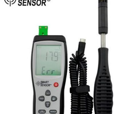
Precision HygroMeter
EGP 1,550.000 exc. vat Read more

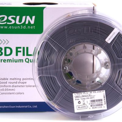
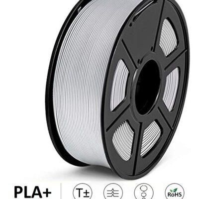
eSUN 3D PLA plus 1.75mm – Grey
EGP 650.000 exc. vat Read more
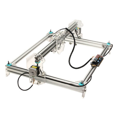
150 x 150 cm Desktop CNC Laser Engraver DIY Kit
EGP 10,000.000 exc. vat Read more
Smd Mini Pushbutton Switch 4P 6x6x2.7mm
EGP 1.000 exc. vat Add to cart
Refund Policy for UGE Electronics “Https://uge-one.com “
1. Returns and Refunds
Thank you for shopping at UGE Electronics “Https://uge-one.com “. If you are not entirely satisfied with your purchase, we’re here to help.
2. Eligibility for Refund
To be eligible for a refund, please make sure that:
– The item was purchased in the last 14 days.
– The item is in the original packaging.
– The item isn’t used or damaged.
3. How to Initiate a Refund
To initiate a refund, please contact our customer support at [[email protected]] or [01066552125]. Provide your order number and details about the product you would like to return.
4. Refund Processing Time
Once we receive your item, we will inspect it and notify you that we have received your returned item. We will immediately notify you on the status of your refund after inspecting the item.
If your return is approved, we will initiate a refund to your credit card (or original method of payment). You will receive the credit within a certain amount of days, depending on your card issuer’s policies.
5. Shipping Costs
Shipping costs are non-refundable. If you receive a refund, the cost of return shipping will be deducted from your refund.
6. Exchanges
If you wish to exchange an item, please contact our customer support. You will be responsible for the return shipping costs, and we will cover the shipping costs of the replacement item.
7. Damaged or Defective Items
If you received a damaged or defective product, please contact us immediately for assistance. We will work with you to resolve the issue promptly.
8. Contact Information
If you have any questions about our Refund Policy, please contact us at [[email protected]].
Important Note: This Return & Refund Policy is applied only for Orders invoiced VIA UGE Electronics, and regarding any Orders has been invoiced VIA any Other Vendor you can check the Return & Refund Policy of this Vendor VIA the Vendor Stroe Page, and it’s not our responsibility for any issue between you and the Vendor.
Product Enquiry
Related products
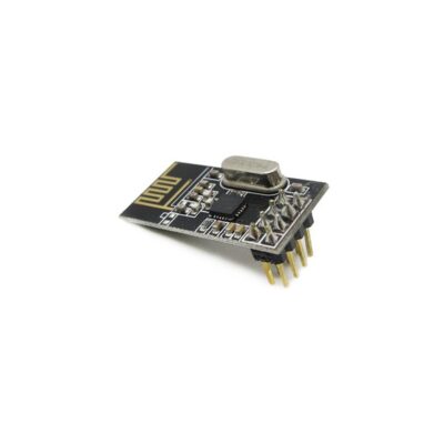
NRF24L01 RF MODULE
EGP 65.000 exc. vat Read more
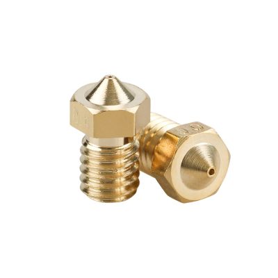
3D Printer E3D Extruder Nozzle 0.4mm for 1.75mm Material
EGP 45.000 exc. vat Add to cart
3D Printer Extrusion MK8 Nozzle (0.2)
EGP 45.000 exc. vat Add to cart
Reviews
There are no reviews yet.