No products in the cart.

CNC Driver DM542 two-phase hybrid stepper motor driver 4.2A
Out of stock
EGP 800.000 exc. vat
Out of stock
Brand:Chinese
Description
Introduction:
DM542 is a type of two-phase hybrid stepping motor driver, The drive voltage of which is from 24VDC to 50VDC. It is designed for use with 2-phase hybrid stepper motor of all kinds with 42mm to 86mm outside diameter and less than 4.0A phase current. This circuit that it adopts is similar to the circuit of servo control which enables the motor run smoothly almost without noise and vibration. Hording torque when DQ542MA run under high speed is also significantly higher than the other two-phase driver, what’s more, the positioning accuracy is also higher. It is widely used in middle and big size numerical control devices such as curving machine, CNC machine, Computer embroider machine, packing machines and so on.
Features:
l High performance, low price
l Average current control, 2-phase sinusoidal output current drive
l Supply voltage from 24VDC to 50VDC
l Opto-isolated signal I/O
l Overvoltage, under voltage, overcorrect, phase short circuit protection
l 15 channels subdivision and automatic idle-current reduction
l 8 channels output phase current setting
l Offline command input terminal
l Motor torque is related with speed, but not related with step/revolution
l High start speed
l High hording torque under high speed
Electrical specification:
|
Input voltage |
24-50VDC |
|
Input current |
< 4A |
|
Output current |
1.0A~4.2A |
|
Consumption |
Consumption:80W; Internal Insurance:6A |
|
Temperature |
Working Temperature -10~45℃; Stocking temperature -40℃~70℃ |
|
Humidity |
Not condensation, no water droplets |
|
gas |
Prohibition of combustible gases and conductive dust |
|
weight |
200G |
1. Pins assignments and description:
1) Connector Pins Configurations
|
Pin Function |
Details |
|
PUL +,PUL- |
Pulse signal, PUL+ is the positive end of pulses input pin PUL- is the negative end of pulse input pin
|
|
DIR+,DIR- |
DIR signal: DIR+ is the positive end of direction input pin DIR- is the negative end of direction input pin |
|
ENBL+
|
Enable signal: ENBL+ is the positive end of direction input pin. This signal is used for enabling/disabling the driver. High level for enabling the driver and low level for disabling the driver. |
|
ENBL- |
ENBL- is the negative end of direction input pin. Usually left unconnected (enabled) |
2) Pins wiring diagram:
PC’s control signals can be active in high and low electrical level. When the high electrical level is active, all control negative signals will be connected together to GND. When low electrical level is active, all control positive signals will be connected together to public port. Now give two examples( Open collector &PNP), please check them:

Fig 1. Input port circuit (Yang connection)
PC open connector output

Fig. 2 Input port circuit ( Yin connection)
PC PNP output
Note: When VCC=5V, R=0
When VCC=12V, R=1K, >1/8W
When VCC=24V, R=2K,>1/8W
R must connect in the control signal part .
3.Function choice ( Using DIP pins to achieve this function)
1) Micro step resolution is set by SW 5,6,7,8 of the DIP switch as shown in the following table:
:
|
SW5 |
OFF |
ON |
OFF |
ON |
OFF |
ON |
OFF |
ON |
OFF |
ON |
OFF |
ON |
OFF |
ON |
OFF |
|
SW6 |
ON |
OFF |
OFF |
ON |
ON |
OFF |
OFF |
ON |
ON |
OFF |
OFF |
ON |
ON |
OFF |
OFF |
|
SW7 |
ON |
ON |
ON |
OFF |
OFF |
OFF |
OFF |
ON |
ON |
ON |
ON |
OFF |
OFF |
OFF |
OFF |
|
SW8 |
ON |
ON |
ON |
ON |
ON |
ON |
ON |
OFF |
OFF |
OFF |
OFF |
OFF |
OFF |
OFF |
OFF |
|
PULSE/REV |
400 |
800 |
1600 |
3200 |
6400 |
12800 |
25600 |
1000 |
2000 |
4000 |
5000 |
8000 |
10000 |
20000 |
25000 |
2) Standstill current setting
SW4 is used for this purpose. OFF meaning that the standstill current is set to be half of the selected dynamic current and ON meaning that standstill is set to be the same as the selected dynamic current.
3) Output current setting:
The first three bits (SW 1, 2, 3)of the DIP switch are used to set the dynamic current. Select a setting
Closest to your motor’s required current
|
Output current (A) |
||||
|
SW1 |
SW2 |
SW3 |
PEAK |
RMS |
|
ON |
ON |
ON |
1.00 |
0.71 |
|
OFF |
ON |
ON |
1.46 |
1.04 |
|
ON |
OFF |
ON |
1.91 |
1.36 |
|
OFF |
OFF |
ON |
2.37 |
1.69 |
|
ON |
ON |
OFF |
2.84 |
2.03 |
|
OFF |
ON |
OFF |
3.31 |
2.36 |
|
ON |
OFF |
OFF |
3.76 |
2.69 |
|
OFF |
OFF |
OFF |
4.20 |
3.00 |
4) Semi-flow function:
Semi-flow function is that there is not step pulse after 500 ms, the driver output current automatically reduced to 70% of rated output current, which is used to prevent motor heat.
4. Power connections
(1)+V、GND:Power Supply.
+V: Power supply, 16~50 VDC, Including voltage fluctuation and EMF voltage. The max current is 5A.
(2) A+ A- B+ B-:Connecting 2 phase stepper motors.
The driver & 2-phase hybrid stepping motor use four-wire connection, the motor can be connected in parallel & series bipolar. As for bipolar connection, it is higher performance with high-speed, but the current of driver is larger (it is 1.73 times more than the motor’s winding current).
Connecting in series, the driver’s current is equal to the motor winding one.
5. Fixing
There should be 20mm of space, it can’t be placed next to other heating devices, to avoid dust, oil mist, corrosive gas, humidity and strong vibration places.
(Unit=mm)

Picture 3
6. Troubleshooting
1, the status on light’s indication
RUN: green, normal work light.
ERR: red, failure light, the motor with phase short-circuit, overvoltage and undervoltage protection.
2 Troubles
|
Alarm indicator
|
Causes |
Measures |
|
LED off turn |
Wrong connection for power |
Check wiring of power |
|
Low-voltages for power |
Enlarge voltage of power |
|
|
Motor doesn’t run, without holding torque |
Wrong connection of stepper motor |
Correct its wiring |
|
RESET signal is effective when offline |
Make RESET ineffective |
|
|
Motor doesn’t run, butmaintains holding torque |
Without input pulse signal |
Adjust PMW & signal level |
|
Motor runs wrong direction |
Wrong wires’ connection |
Change connection for any of 2 wires |
|
Wrong input direction signal |
Change direction setting |
|
|
Motor’s holding torque is too small |
Too small relative to current setting |
Correct rated current setting |
|
Acceleration is too fast |
Reduce the acceleration |
|
|
Motor stalls |
Rule out mechanical failure |
|
|
Driver does not match with the motor |
Change a suitable driver |
7. Driver Wiring
A complete stepper motor control system should contain stepper drives, DC power supply and controller (pulse source). The following is a typical system wiring diagram

Additional information
| Weight | 0.37 kg |
|---|
Brand
Chinese
Chinese

Chinese
You must be logged in to post a review.
Smd Chip Ceramic Capacitor size 0603 220PF
EGP 0.800 exc. vat Add to cart
Four Channel RF Wireless Remote Kit 4ch TTL Output
EGP 185.000 exc. vat Read more
SM3113N SMD N-Mosfet 30V 85A TO252
EGP 12.000 exc. vat Read more
NEMA 17 Stepper Motor JK42HS48-1684-08AF With 1M Cable
EGP 290.000 exc. vat Read more
SMD Chip Resistor size 1206 33K Ohm
EGP 0.500 exc. vat Read more
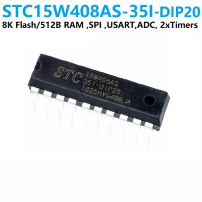
STC Microcontroller STC15W408AS-35I-DIP20
EGP 91.000 exc. vat Add to cart
Refund Policy for UGE Electronics “Https://uge-one.com “
1. Returns and Refunds
Thank you for shopping at UGE Electronics “Https://uge-one.com “. If you are not entirely satisfied with your purchase, we’re here to help.
2. Eligibility for Refund
To be eligible for a refund, please make sure that:
– The item was purchased in the last 14 days.
– The item is in the original packaging.
– The item isn’t used or damaged.
3. How to Initiate a Refund
To initiate a refund, please contact our customer support at [[email protected]] or [01066552125]. Provide your order number and details about the product you would like to return.
4. Refund Processing Time
Once we receive your item, we will inspect it and notify you that we have received your returned item. We will immediately notify you on the status of your refund after inspecting the item.
If your return is approved, we will initiate a refund to your credit card (or original method of payment). You will receive the credit within a certain amount of days, depending on your card issuer’s policies.
5. Shipping Costs
Shipping costs are non-refundable. If you receive a refund, the cost of return shipping will be deducted from your refund.
6. Exchanges
If you wish to exchange an item, please contact our customer support. You will be responsible for the return shipping costs, and we will cover the shipping costs of the replacement item.
7. Damaged or Defective Items
If you received a damaged or defective product, please contact us immediately for assistance. We will work with you to resolve the issue promptly.
8. Contact Information
If you have any questions about our Refund Policy, please contact us at [[email protected]].
Important Note: This Return & Refund Policy is applied only for Orders invoiced VIA UGE Electronics, and regarding any Orders has been invoiced VIA any Other Vendor you can check the Return & Refund Policy of this Vendor VIA the Vendor Stroe Page, and it’s not our responsibility for any issue between you and the Vendor.
Product Enquiry
Related products
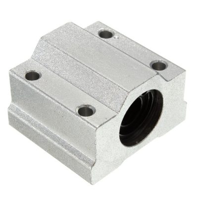
3D printer CNC SCS16UU Linear Motion Ball Bearing Slide Block
EGP 200.000 exc. vat Add to cart
3D printer CNC SCS12UU Linear Motion Ball Bearing Slide Block
EGP 195.000 exc. vat Add to cart
3D printer CNC SCS10UU Linear Motion Ball Bearing Slide Block
EGP 190.000 exc. vat Add to cart
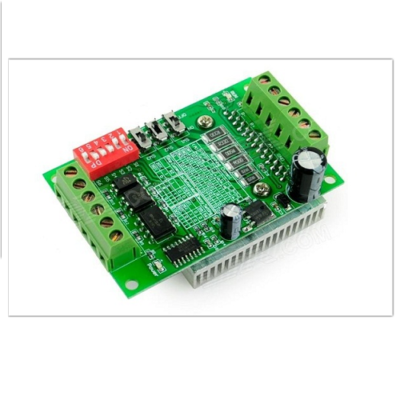
TB6560 Stepper Motor Driver 3A
EGP 185.000 exc. vat Read more
Reviews
There are no reviews yet.