No products in the cart.

CNC Driver DM860 two-phase hybrid stepper motor driver 7.2A
Out of stock
EGP 1,300.000 exc. vat
Out of stock
Brand:Chinese
Description
Introduction:
DM860H is a type of two-phase hybrid stepping motor driver. The drive voltage of which is from 24VDC to 80VDC or 18-50 AC. It is designed for use with 2-phase hybrid stepper motor of all kinds with 57mm to 110mm outside diameter and less than 7.8A phase current. This circuit that it adopts is similar to the circuit of servo control which enables the motor run smoothly almost without noise and vibration. Hording torque when DQ860MA run under high speed is also significantly higher than the other 2-phase driver, what’s more, the DM860 positioning accuracy is also higher. It is widely used in middle and big size numerical control devices such as curving machine, CNC machine, and computer embroider machine, packing machines and so on.
Features:
l High performance, low price
l Average current control, DM860 2-phase sinusoidal output current drive inside
l DM860 Supply voltage from 24VDC to 80VDC / 18VAC-50VAC
l Opto-isolated signal I/O
l Overvoltage, under voltage, overcorrect, phase short circuit protection
l 14 channels subdivision and automatic idle-current reduction
l 8 channels output phase current setting
l Offline command input terminal
l Motor torque is related with speed, but not related with step/revolution
l High start speed
l High hording torque under high speed
Electrical specification:
|
Input voltage |
24-80VDC |
|
Input current |
< 6A |
|
Output current |
2.8A~7.8A |
|
Consumption |
Consumption:80W; Internal Insurance:10A |
|
Temperature |
Working Temperature -10~45℃; Stocking temperature -40℃~70℃ |
|
Humidity |
Not condensation, no water droplets |
|
gas |
Prohibition of combustible gases and conductive dust |
|
weight |
500G |
Pins assignments and description:
1) Connector Pins Configurations
|
Pin Function |
Details |
|
PUL +,PUL- |
Pulse signal, PUL+ is the positive end of pulses input pin PUL- is the negative end of pulse input pin
|
|
DIR+,DIR- |
DIR signal: DIR+ is the positive end of direction input pin DIR- is the negative end of direction input pin |
|
ENBL+
|
Enable signal: ENBL+ is the positive end of direction input pin. This signal is used for enabling/disabling the driver. High level for enabling the driver and low level for disabling the driver. |
|
ENBL- |
ENBL- is the negative end of direction input pin. Usually left unconnected (enabled) |
2) Pins wiring diagram:
PC’s control signals can be active in high and low electrical level. When the high electrical level is active, all control negative signals will be connected together to GND. When low electrical level is active, all control positive signals will be connected together to public port. Now give two examples( Open collector &PNP), please check them:

Fig 1. Input port circuit (Yang connection)
PC open connector output
 Fig. 2 Input port circuit ( Yin connection)
PC PNP output
Note: When VCC=5V, R=0
When VCC=12V, R=1K, >1/8W
When VCC=24V, R=2K,>1/8W
R must connect in the control signal part .
3.Function choice ( Using DIP pins to achieve this function)
1) Micro step resolution is set by SW 5,6,7,8 of the DIP switch as shown in the following table:
|
SW5 |
ON |
OFF |
ON |
OFF |
ON |
OFF |
ON |
OFF |
ON |
OFF |
ON |
OFF |
ON |
OFF |
|
SW6 |
ON |
ON |
OFF |
OFF |
ON |
ON |
OFF |
OFF |
ON |
ON |
OFF |
OFF |
ON |
ON |
|
SW7 |
ON |
ON |
ON |
ON |
OFF |
OFF |
OFF |
OFF |
ON |
ON |
ON |
ON |
OFF |
OFF |
|
SW8 |
ON |
ON |
ON |
ON |
ON |
ON |
ON |
ON |
OFF |
OFF |
OFF |
OFF |
OFF |
OFF |
|
PULSE/REV |
400 |
800 |
1600 |
3200 |
6400 |
12800 |
25600 |
51200 |
1000 |
2000 |
5000 |
10000 |
25000 |
50000 |
2) Standstill current setting
SW4 is used for this purpose. OFF meaning that the standstill current is set to be half of the selected dynamic current and ON meaning that standstill is set to be the same as the selected dynamic current.
3) Output current setting:
The first three bits (SW 1, 2, 3)of the DIP switch are used to set the dynamic current. Select a setting
Closest to your motor’s required current
|
Output current (A) |
||||
|
SW1 |
SW2 |
SW3 |
PEAK |
RMS |
|
ON |
ON |
ON |
2.40 |
2.00 |
|
OFF |
ON |
ON |
3.08 |
2.570 |
|
ON |
OFF |
ON |
3.77 |
3.14 |
|
OFF |
OFF |
ON |
4.45 |
3.50 |
|
ON |
ON |
OFF |
5.14 |
4.00 |
|
OFF |
ON |
OFF |
5.83 |
4.60 |
|
ON |
OFF |
OFF |
6.52 |
5.43 |
|
OFF |
OFF |
OFF |
7.20 |
6.00 |
4) Semi-flow function:
Semi-flow function is that there is not step pulse after200 ms, the driver output current automatically reduced to 40% of rated output current, which is used to prevent motor heat.
4. Pins of motor & power:
|
Motor and power pins |
1 |
A+ |
Motors wiring |
|
|
2 |
A- |
|||
|
3 |
B+ |
|||
|
4 |
B- |
|||
|
5,6 |
DC+ DC- |
Power supply |
Power supply :DC24-80VDC / AC 18-50 The peak input current can not up to 6A |
5. Mechanical Specification:
To have 20mm of space around ,cannot be placed next to other heating devices. What’s more, avoid dust, oil mist, corrosive gas, heavy humidity and high vibration. (Unit=mm)

6. Adjustment of troubleshooting
1) , the status on light’s indication
PWR: green, normal work light.
ALM: red, failure light, the motor with phase short-circuit, overvoltage and under-voltage protection.
2) Troubles
|
Alarm indicator
|
Reasons |
Measures |
|
LED off turn |
Wrong connection for power |
Check wiring of power |
|
Low-voltages for power |
Enlarge voltage of power |
|
|
Motor doesn’t run, without holding torque |
Wrong connection of stepper motor |
Correct its wiring |
|
RESET signal is effective when offline |
Make RESET ineffective |
|
|
Motor doesn’t run, but maintains holding torque |
Without input pulse signal |
Adjust PMW & signal level |
|
Motor runs wrong direction |
Wrong wires’ connection |
Change connection for any of 2 wires |
|
Wrong input direction signal |
Change direction setting |
|
|
Motor’s holding torque is too small |
Too small relative to current setting |
Correct rated current setting |
|
Acceleration is too fast |
Reduce the acceleration |
|
|
Motor stalls |
Rule out mechanical failure |
|
|
Driver does not match with the motor |
Change a suitable driver |
7. Driver wiring
A complete stepper motor control system should contain stepper drives, DC power supply and controller (pulse source). The following is a typical system wiring diagram

Additional information
| Weight | 0.054 kg |
|---|
Brand
Chinese
Chinese

Chinese
You must be logged in to post a review.
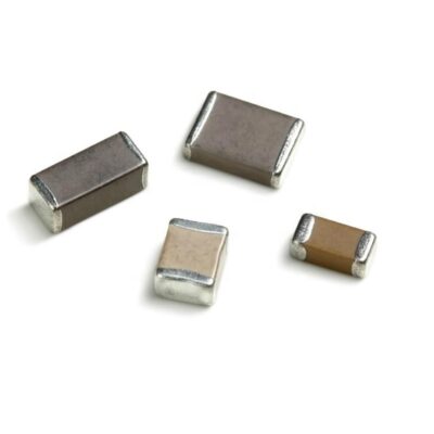
Smd Chip Capacitor size 1206 89pF
EGP 1.000 exc. vat Read more
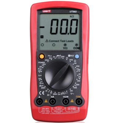
Electrical Digital Multimeter UNI-T UT-58D(UT58D)
EGP 665.000 exc. vat Read more
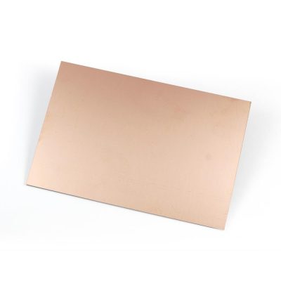
PCB FR4 Copper Board 10×15 Double Side
EGP 70.000 exc. vat Add to cart
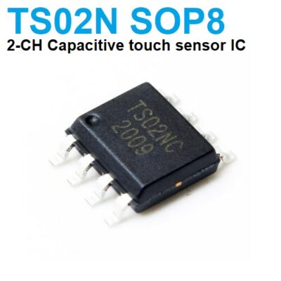
TS02N 2-CH Capacitive touch sensor IC SMD 8PIN
EGP 31.000 exc. vat Add to cart
Refund Policy for UGE Electronics “Https://uge-one.com “
1. Returns and Refunds
Thank you for shopping at UGE Electronics “Https://uge-one.com “. If you are not entirely satisfied with your purchase, we’re here to help.
2. Eligibility for Refund
To be eligible for a refund, please make sure that:
– The item was purchased in the last 14 days.
– The item is in the original packaging.
– The item isn’t used or damaged.
3. How to Initiate a Refund
To initiate a refund, please contact our customer support at [[email protected]] or [01066552125]. Provide your order number and details about the product you would like to return.
4. Refund Processing Time
Once we receive your item, we will inspect it and notify you that we have received your returned item. We will immediately notify you on the status of your refund after inspecting the item.
If your return is approved, we will initiate a refund to your credit card (or original method of payment). You will receive the credit within a certain amount of days, depending on your card issuer’s policies.
5. Shipping Costs
Shipping costs are non-refundable. If you receive a refund, the cost of return shipping will be deducted from your refund.
6. Exchanges
If you wish to exchange an item, please contact our customer support. You will be responsible for the return shipping costs, and we will cover the shipping costs of the replacement item.
7. Damaged or Defective Items
If you received a damaged or defective product, please contact us immediately for assistance. We will work with you to resolve the issue promptly.
8. Contact Information
If you have any questions about our Refund Policy, please contact us at [[email protected]].
Important Note: This Return & Refund Policy is applied only for Orders invoiced VIA UGE Electronics, and regarding any Orders has been invoiced VIA any Other Vendor you can check the Return & Refund Policy of this Vendor VIA the Vendor Stroe Page, and it’s not our responsibility for any issue between you and the Vendor.
Product Enquiry
Related products
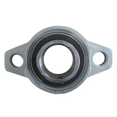
END Support Pillow Block Bearing 8mm KFL08
EGP 30.000 exc. vat Read more
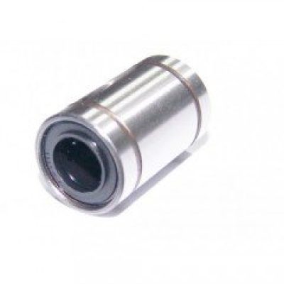
3D printer LM10UU 10mm Linear Ball Bearing
EGP 60.000 exc. vat Add to cart
USB CNC Controller
EGP 1,000.000 exc. vat Read more
5 Axis CNC Breakout Interface Board
EGP 240.000 exc. vat Read more
Reviews
There are no reviews yet.