Description
SIT1051T/3 High Speed CAN FD bus transceiver chip SOP8
SIT1051T/3 High-performance CAN FD transceiver chip with 3.3V logic input power supply
SIT1051T/3 is a high-performance CAN FD transceiver chip with a 3.3V logic input power supply, which can be used in trucks, buses, cars, industrial control and other fields. The bus withstand voltage reaches more than ±70V, supports 5Mbps CAN FD flexible data rate, and has the ability to perform differential signal transmission between the bus and the CAN protocol controller…
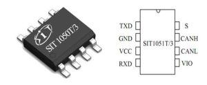
Figure 1 SIT1051T/3 pin diagram
The main features of the SIT1051 chip are as follows :
- Bus voltage withstand capability -70V~70V;
- Common mode voltage is -30~30V;
- Supports 5Mbps CAN FD (Flexible Data Rate);
- Performance meets or exceeds the “ISO 11898” standard, providing SOP8
- Driver (TXD) dominant timeout function, silent receiving mode;, built-in over-temperature protection function;
- The SIT1051T/3 model I/O voltage range supports 3.3V and 5V MCUs;
- Under voltage protection on VCC and VIO power pins;
- Passed -40℃~150℃ high and low temperature aging test, meeting the application range of industrial control and vehicle;
- High anti-electromagnetic interference capability, unpowered nodes do not interfere with the bus;
SIT1051T/3 is a high-performance CAN FD transceiver chip that meets international standards. Its typical application circuit is as follows:
1. Split terminal
The concept of split termination is shown in the figure. The terminal resistance of the bus end node is divided into two equal resistances, that is, two 60Ω resistors are used to replace a 120Ω terminal resistance, and a capacitor C (1nF~100nF) is connected to the ground at the middle tapping point of the terminal. This connection method can effectively reduce radiation and make the system more anti-interference. Other stub nodes on the bus can also use similar split terminal configurations. The resistance selection of the stub node must make the bus load including all terminal resistances within the specified range of 50Ω~65Ω. For example, when there are 10 nodes, 8 stub nodes and 2 bus terminal nodes, the resistance value of the typical stub node is 1.3kΩ.
If the EMC performance after using the split terminal is still not sufficient, you can also choose to use ground matching capacitors and common mode inductors (inductive chokes).
If split terminals are not required, terminal resistors can be directly connected.
2. Ground matching capacitor
A pair of matching capacitors from CANH and CANL output to GND is used to improve the performance of anti-electromagnetic interference. The impedance of the corresponding noise source and the capacitance of CANH and CANL to ground form an RC low-pass filter. The capacitance value must be determined by the number of nodes and the data transmission frequency. Generally, <100pF is selected. If an external ESD protection device is connected, the capacitance value can be appropriately reduced or omitted. The series resistor in the figure can adjust the performance of the low-pass filter formed with the capacitance to ground, but the resistance value should not be too large, resulting in a significant reduction in the dominant differential voltage value.
3. Common mode inductor
The common mode inductor has a high impedance to the common mode signal and a low impedance to the differential signal. Therefore, the common mode signal generated by RF noise and/or the imperfect symmetry of the transceiver driver is significantly attenuated. Therefore, the inductive choke can reduce radiation to improve the interference immunity.
If the goal is to increase interference immunity first, it is recommended to place a capacitor to ground between the transceiver and the common mode choke. If, on the other hand, the goal is to reduce radiation, it is recommended to place the capacitor between the choke and the split terminal.
4. ESD protection devices
If the system needs to work normally within the common mode range of -12V~+12V, a bidirectional ESD protection device must be selected. If the common mode variation range is positive, a unidirectional diode ESD protection device can be selected. When the system communication rate is high, it is best to select an ESD protection device with fast response speed and small capacitance value.








Reviews
There are no reviews yet.