Description
PCB For DIY Line Tracking Car
1 Design Overview
a DIY simple line-Tracking and obstacle-avoiding car, requiring the use of digital circuits to implement the tracking function and analog circuits to implement the obstacle avoidance function.
2 Overall design plan
According to the design requirements, a 74HC00N NAND gate is used in conjunction with an infrared emitting tube. By judging whether infrared light is detected, the receiving tube is turned on or not, and the signal is input into the NAND gate to realize digital circuit tracking.
Using the LM393 comparator with the infrared emitting tube, it is also to determine whether the infrared light is detected in front and whether the receiving tube is turned on. The two sets of signals are input into the comparator for comparison to realize the obstacle avoidance function of the analog circuit.
3 Circuit composition
3.1 Power Circuit
The device is powered by two AA batteries, each with a voltage of 1.5V. Connecting two batteries in series provides a voltage of 3V, meeting the chip’s minimum power requirements. A three-position slide switch allows for switching between tracking and obstacle avoidance functions. Capacitors C1 and C3 are filter capacitors for energy storage. When the motor starts operating, transient currents are high, and the 100uF capacitor helps discharge the batteries.
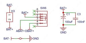
Figure 1 Power supply circuit
3.2 Motor Drive Circuit
The positive pole of the battery is connected to the positive pole of the motor, and the negative pole is controlled and turned on through a transistor. When a digital tracking or analog obstacle avoidance signal is generated, the base of the transistor is controlled to control the operation of the left and right tires, thereby realizing the tracking and obstacle avoidance functions.
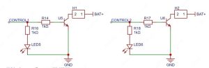
Figure 2 Motor drive circuit
3.3 Digital Signal Tracking
U2 and U3 are infrared emitting tubes, and LED3 and LED4 are corresponding infrared receiving tubes, which are installed on both sides of the front wheels. The principle analysis is as follows:
- When the car starts to move and hits the white paper, the infrared light is reflected and received by the receiving tube, which turns on. When it hits the black line, the infrared light is absorbed and the receiving tube turns off.
- 74HC00N is a NAND gate. When it touches the black line, the receiving tube is cut off, CNT1 outputs a high level, corresponding to OUT1 outputs a low level, and OUT3 outputs a high level;
- At this time, the high level output by OUT3 will flow through the motor transistor, controlling the three-stage conduction and the motor rotation;
The vehicle continuously encounters black and white lines on the map route, thereby continuously turning on and off the transistor, realizing the line patrol function around the black line track.
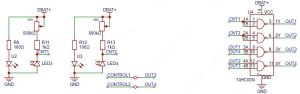
Figure 3 Digital signal tracking circuit
3.4 Analog Signal Obstacle Avoidance
IR1 and IR2 are infrared transmitting tubes, and CGQ1 and CGQ2 are corresponding infrared receiving tubes, which are installed on both sides of the front of the vehicle. The schematic diagram is analyzed as follows:
- When the vehicle is running, there is no obstacle in front, the infrared transmission signal will not be received, the receiving tube is cut off, the 393 comparator’s non-inverting input terminal is the battery voltage, and the voltage is greater than the inverting input terminal. At this time, the 393 comparator outputs a high level to control the vehicle to move forward.
- When there is an obstacle in front of the car, the infrared emission signal is received by the receiving tube, the receiving tube is turned on, 393 is relatively strong, the same-direction input end is low level, and the voltage is less than the inverting input end. At this time, 393 comparator outputs a low level, the corresponding wheel stops running, thereby achieving steering.
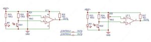
Figure 4 Analog signal tracking circuit







Reviews
There are no reviews yet.