Description
Overview
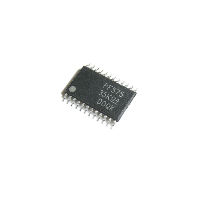
The PCF8575PWR from Texas Instruments is a 16-bit remote I/O expander that adds 16 general-purpose digital I/O lines to a microcontroller through a simple I²C/SMBus interface. It is designed for applications where additional GPIO pins are required without using more MCU pins.
The device operates from 2.5 V to 5.5 V, supports I²C communication up to 400 kHz, and provides an interrupt output for detecting changes on the input ports. Up to eight PCF8575 devices can share the same I²C bus using the three hardware address pins.
Key Features
- 16-bit GPIO expansion
- I²C / SMBus interface
- Up to 400 kHz I²C bus speed
- Operating voltage: 2.5–5.5 V
- 8 selectable I²C addresses
- Open-drain interrupt output
- Quasi-bidirectional I/O architecture
- No separate direction registers required
- Latched outputs
- Suitable for directly driving LEDs
- Low standby current
- Compact TSSOP-24 package
- −40°C to +85°C operating temperature range
Technical Specifications
| Parameter |
Specification |
| Part Number |
PCF8575PWR |
| Manufacturer |
Texas Instruments |
| Device Type |
16-Bit I/O Expander |
| Number of I/O Pins |
16 |
| Interface |
I²C / SMBus |
| Maximum I²C Frequency |
400 kHz |
| Supply Voltage |
2.5–5.5 V |
| Number of I²C Addresses |
8 |
| Address Pins |
A0, A1, A2 |
| Interrupt |
Open-drain INT output |
| I/O Type |
Quasi-bidirectional |
| Operating Temperature |
−40°C to +85°C |
| Package |
TSSOP-24 (PW) |
| Mounting |
Surface Mount (SMD) |
TI currently lists PCF8575PWR as an active part number in the 24-pin TSSOP package.
I/O Configuration
The 16 GPIOs are organized into two 8-bit ports:
The PCF8575 uses a quasi-bidirectional I/O architecture, allowing each pin to function as either an input or output without a conventional direction-control register. After power-on, the I/O pins are HIGH.
I²C Addressing
Three hardware address pins provide 8 possible I²C addresses, allowing multiple PCF8575 devices to operate on the same I²C bus.
This makes it possible to expand a system by up to 128 additional I/O pins using eight devices, subject to bus loading and system design considerations.
Interrupt
The INT output is an open-drain interrupt signal that can notify the host MCU when an input state changes. This can reduce the need for continuously polling all 16 inputs.
Pin Configuration
| Pin |
Function |
| 1–8 |
P00–P07 GPIO |
| 9 |
VSS / GND |
| 10 |
P10 |
| 11 |
P11 |
| 12 |
P12 |
| 13 |
P13 |
| 14 |
P14 |
| 15 |
P15 |
| 16 |
P16 |
| 17 |
P17 |
| 18 |
INT |
| 19 |
A1 |
| 20 |
A2 |
| 21 |
A0 |
| 22 |
SCL |
| 23 |
SDA |
| 24 |
VCC |
Verify the pin numbering against the TI datasheet when creating the PCB footprint or assembly documentation.
Power & Programming
- Supply voltage: 2.5–5.5 V
- Typical applications include 3.3 V and 5 V systems.
- No programming is required.
- The device is controlled through the I²C interface.
- External pull-up resistors are required for the I²C SDA and SCL lines.
- The INT output is open-drain and normally requires a pull-up resistor when used.
Applications
- GPIO expansion for microcontrollers
- Arduino projects
- ESP32 and ESP8266 projects
- STM32 applications
- Relay and LED control
- Keypad and button interfaces
- LCD and display control
- Industrial control systems
- Robotics
- Embedded systems
- I²C-based peripheral expansion
What’s Included
- 1 × Texas Instruments PCF8575PWR 16-Bit I²C I/O Expander IC
- Package: TSSOP-24
- Surface-mount component
Notes
- PCF8575PWR is the active TSSOP-24 version. The older PCF8575PW ordering code is obsolete and has been replaced by PCF8575PWR.
- The PCF8575 is different from the PCF8574, which provides only 8 I/O pins.
- The I/O pins are not equivalent to standard push-pull GPIOs in every operating condition because the PCF8575 uses a quasi-bidirectional architecture.
- When driving loads such as relays, motors, or other high-current devices, use an appropriate transistor, MOSFET, driver IC, or relay-driver circuit rather than connecting the load directly to the PCF8575.
- TSSOP-24 (PW) is the correct package designation for PCF8575PWR.








Reviews
There are no reviews yet.