Description
Introduction
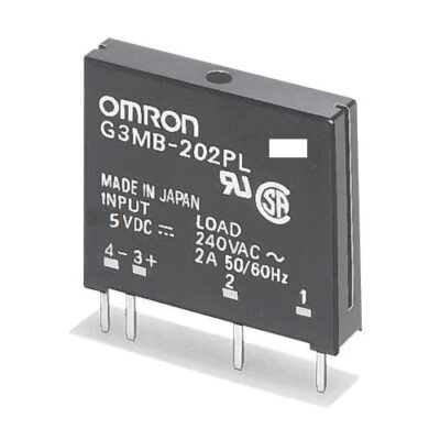
A solid state relay (SSR) is just what it sounds like; an IC that acts like a mechanical relay. They allow you to control high-voltage AC loads from lower voltage DC control circuitry. They accomplish this by using infrared light as the ‘contact,’ a solid-state relay SSR is really just an IR LED and a phototriac sealed up into a little box.
Solid state relays, have several advantages over mechanical relays. One such advantage is that they can be switched by a much lower voltage and at a much lower current than most mechanical relays. Also, because there’s no moving contacts, solid state relays can be switched much faster and for much longer periods without wearing out.
Features:
- Size: 25*34*25 (Length*Width*Height)
- Input voltage: 12VDC, Maximum Output Current: 2A, Maximum Output Voltage: 240VAC
- Input Voltage of Control Signal: 0-2.5V (low level state), the relay will be on; 3-5V (high level state), the relay will be off.
- Triggered at low level.
SSR Ports Description:
Input:
DC+: Connected to positive supply voltage (supply power according to relay voltage)
DC-: Connected to negative supply voltage
CH1:Signal triggering terminal of relay module
The meaning of high and low level:
Triggered at high level means a forward voltage exists between signal triggering terminal (CH1) and negative supply voltage. It generally connects positive supply voltage and triggering terminal together. When triggering terminal has positive supply voltage or reaches triggering voltage, the relay will pull in.
While triggered at low level means the voltage between the signal triggering terminal (CH1) and negative supply voltage is 0V, or the voltage at the triggering terminal is lower than positive supply voltage. If it lowers to a triggering voltage, the relay will pull in. It generally connects negative supply voltage and triggering terminal together.
Output:
Connect a load: 2 A, 240 VAC
Input Rating:
| Operating Range |
Operating Current |
Input Impedance |
Trigger Voltage |
Reset Voltage Rating |
| 12VDC |
12.5mA |
440 Ω ±20% |
3.3~5v |
1V |
Output (Under 25℃ environmental temperature)
| Rated Load Voltage |
Load Voltage Range |
Load Current |
Surge Current |
| AC100~240V 50/60Hz |
AC75~264V 50/60Hz |
0.10 to 2 A |
30 A (60 Hz, 1 cycle) |
SSR Application
General purpose
Testing Experiment
Experiment Principle:
When a low level is supplied to signal terminal of the solid state relay, the LED at the output terminal will light up. Otherwise, it will turn off. If a periodic high and low level is supplied to the signal terminal, you can see the LED will cycle between on and off.
Experiment Steps:
Connect the signal terminal (CH1) of solid state relay to digital port 7 of the our Uno board, and connect an LED at the output terminal. Upload the following code, then you can see the LED cycle between on and off.
/**************************************************************Arduino CODE******************************************************/
#define RelayPIN 7
// the setup function runs once when you press reset or power the board
void setup() {
// initialize digital pin LED_BUILTIN as an output.
pinMode(RelayPIN, OUTPUT);
}
// the loop function runs over and over again forever
void loop() {
digitalWrite(RelayPIN, HIGH); // turn the LED on (HIGH is the voltage level)
delay(1000); // wait for a second
digitalWrite(RelayPIN, LOW); // turn the LED off by making the voltage LOW
delay(1000); // wait for a second
}









Reviews
There are no reviews yet.