No products in the cart.

1 Channel 5V Solid State Relay Active Low SSR Module
Out of stock
EGP 100.000 exc. vat
Out of stock
Brand:UGE Electronics
Description
Introduction
A solid state relay (SSR) is just what it sounds like; an IC that acts like a mechanical relay. They allow you to control high-voltage AC loads from lower voltage DC control circuitry. They accomplish this by using infrared light as the ‘contact,’ a solid-state relay SSR is really just an IR LED and a phototriac sealed up into a little box.
Solid state relays, have several advantages over mechanical relays. One such advantage is that they can be switched by a much lower voltage and at a much lower current than most mechanical relays. Also, because there’s no moving contacts, solid state relays can be switched much faster and for much longer periods without wearing out.
Features:
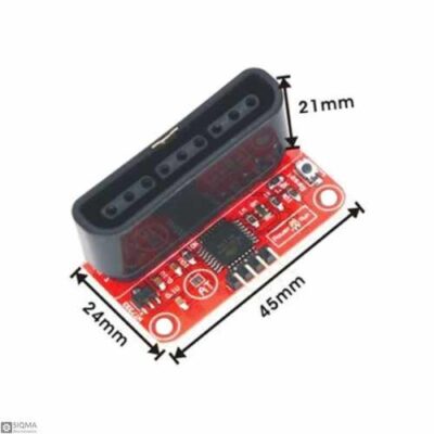
- Size: 25*34*25 (Length*Width*Height)
- Input voltage: 5VDC, Maximum Output Current: 2A, Maximum Output Voltage: 240VAC
- Input Voltage of Control Signal: 0-2.5V (low level state), the relay will be on; 3-5V (high level state), the relay will be off.
- Triggered at low level.
SSR Ports Description:
Input:
DC+: Connected to positive supply voltage (supply power according to relay voltage)
DC-: Connected to negative supply voltage
CH1:Signal triggering terminal of relay module
The meaning of high and low level:
Triggered at high level means a forward voltage exists between signal triggering terminal (CH1) and negative supply voltage. It generally connects positive supply voltage and triggering terminal together. When triggering terminal has positive supply voltage or reaches triggering voltage, the relay will pull in.
While triggered at low level means the voltage between the signal triggering terminal (CH1) and negative supply voltage is 0V, or the voltage at the triggering terminal is lower than positive supply voltage. If it lowers to a triggering voltage, the relay will pull in. It generally connects negative supply voltage and triggering terminal together.
Output:
Connect a load: 2 A, 240 VAC
Input Rating:
| Operating Range | Operating Current | Input Impedance | Trigger Voltage | Reset Voltage Rating |
| 5VDC | 12.5mA | 440 Ω ±20% | 3.3~5v | 1V |
Output (Under 25℃ environmental temperature)
| Rated Load Voltage | Load Voltage Range | Load Current | Surge Current |
| AC100~240V 50/60Hz | AC75~264V 50/60Hz | 0.10 to 2 A | 30 A (60 Hz, 1 cycle) |
SSR Application
General purpose
Testing Experiment
Experiment Principle:
When a low level is supplied to signal terminal of the solid state relay, the LED at the output terminal will light up. Otherwise, it will turn off. If a periodic high and low level is supplied to the signal terminal, you can see the LED will cycle between on and off.
Experiment Steps:
Connect the signal terminal (CH1) of solid state relay to digital port 7 of the SunFounder Uno board, and connect an LED at the output terminal. Upload the following code, then you can see the LED cycle between on and off.
Code
/********************************************** const int relayPin =7; //the Signal Pin of relay module attach to /**********************************************/ void setup() { pinMode(relayPin, OUTPUT); //initialize relay as an output } /***********************************************/ void loop() { digitalWrite(relayPin, LOW); //Close the relay delay(3000); //wait for 3 second digitalWrite(relayPin, HIGH); //disconnect the relay delay(2000); //wait for 2 second } //*************************************************/
Additional information
| Weight | 0.009 kg |
|---|
Brand
UGE Electronics
UGE Electronics
UGE Electronics
You must be logged in to post a review.
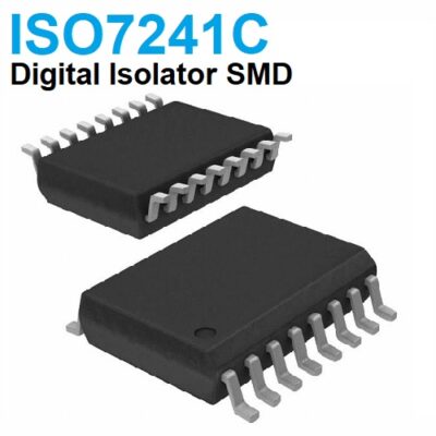
ISO7241CDW Quad-channel 25-Mbps digital isolator
EGP 185.000 exc. vat Add to cart
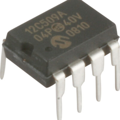
PIC12C509A-04P
EGP 25.000 exc. vat Read more

Potentiometer POT SM 1K
EGP 3.500 exc. vat Read more
0603 SMD laminated inductor 6.8uH
EGP 1.000 exc. vat Add to cart
Refund Policy for UGE Electronics “Https://uge-one.com “
1. Returns and Refunds
Thank you for shopping at UGE Electronics “Https://uge-one.com “. If you are not entirely satisfied with your purchase, we’re here to help.
2. Eligibility for Refund
To be eligible for a refund, please make sure that:
– The item was purchased in the last 14 days.
– The item is in the original packaging.
– The item isn’t used or damaged.
3. How to Initiate a Refund
To initiate a refund, please contact our customer support at [[email protected]] or [01066552125]. Provide your order number and details about the product you would like to return.
4. Refund Processing Time
Once we receive your item, we will inspect it and notify you that we have received your returned item. We will immediately notify you on the status of your refund after inspecting the item.
If your return is approved, we will initiate a refund to your credit card (or original method of payment). You will receive the credit within a certain amount of days, depending on your card issuer’s policies.
5. Shipping Costs
Shipping costs are non-refundable. If you receive a refund, the cost of return shipping will be deducted from your refund.
6. Exchanges
If you wish to exchange an item, please contact our customer support. You will be responsible for the return shipping costs, and we will cover the shipping costs of the replacement item.
7. Damaged or Defective Items
If you received a damaged or defective product, please contact us immediately for assistance. We will work with you to resolve the issue promptly.
8. Contact Information
If you have any questions about our Refund Policy, please contact us at [[email protected]].
Important Note: This Return & Refund Policy is applied only for Orders invoiced VIA UGE Electronics, and regarding any Orders has been invoiced VIA any Other Vendor you can check the Return & Refund Policy of this Vendor VIA the Vendor Stroe Page, and it’s not our responsibility for any issue between you and the Vendor.
Product Enquiry
Related products
BREADBOARD POWER SUPPLY MODULE
EGP 30.000 exc. vat Read more
RS485-TTL Converter Interface Module 5V
EGP 140.000 exc. vat Add to cart
Arduino MP3 Module
EGP 120.000 exc. vat Read more
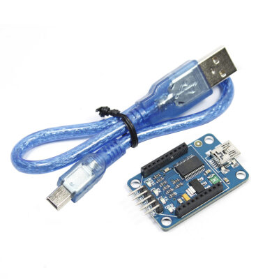
PS2/PS3 wireless controller to serial UART adapter
EGP 150.000 exc. vat Add to cart
Reviews
There are no reviews yet.