Description
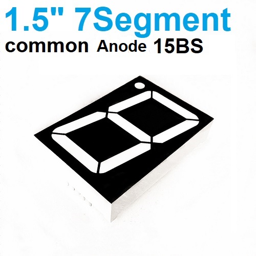
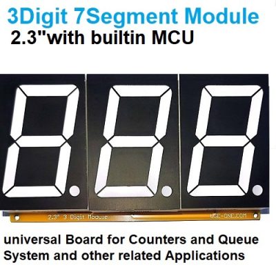
1.5″ Common Anode 7-Segment LED Display (15BS) – Key Specifications
1. Basic Parameters
- Display Type: Single digit, 7-segment + decimal point (8 total LEDs)
- Color: Red (standard brightness)
- Configuration: Common Anode (+V connected to common pin)
- Character Height: 1.5 inch (38.1mm)
- Digit Format: 0-9, A-F (hexadecimal capable)
2. Electrical Characteristics
- Forward Voltage (Vf): 1.8-2.2V per segment (typical @20mA)
- Forward Current (If): 20mA per segment (recommended)
- Max Continuous Current: 25mA per segment
- Power Dissipation: 0.5W max (all segments + DP on)
- Voltage Drop (Common Anode): ~1.5V
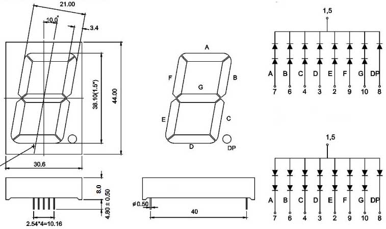
3. Pin Configuration (10-pin, Dual-in-line)
Pin 2: Segment D
Pin 3: Common Anode (COM)
Pin 4: Segment C
Pin 5: Decimal Point (DP)
Pin 6: Segment B
Pin 7: Segment A
Pin 8: Common Anode (COM)
Pin 9: Segment F
Pin 10: Segment G
Note: Pins 3 & 8 are internally connected
4. Optical Specifications
- Luminance: 500-800 mcd (typical)
- Viewing Angle: 60° (wide angle)
- Wavelength: 620-630nm (red)
5. Physical Dimensions
- PCB Size: ~40x20mm (varies by manufacturer)
- Segment Width: ~5mm
- Digit Thickness: ~8mm
- Pin Length: ~12mm (breadboard-friendly)
6. Thermal & Environmental
- Operating Temp: -30°C to +70°C
- Storage Temp: -40°C to +85°C
- Material: Plastic case, epoxy-filled
7. Recommended Circuit
- Current-Limiting Resistors: 150Ω per segment (for 5V supply)
- Driver IC: CD4511 (BCD-to-7-segment) or 74HC595 shift register
8. Applications
- Digital clocks
- Instrument panels
- DIY counters
- Industrial displays
9. Manufacturer Variant:
Why Choose Common Anode?
✅ Easier interface with NPN transistors
✅ Better for multiplexing multiple displays
✅ Compatible with most microcontroller GPIO
Design Notes
- Always use current-limiting resistors (calculations below)
- For 5V systems:
- Resistor = (5V – Vf – Vce) / If ≈ (5-2-0.2)/0.02 = 140Ω → use 150Ω
- Multiplexing tip: Keep duty cycle >1ms per digit to avoid flicker









Reviews
There are no reviews yet.