No products in the cart.

AC short Circuit Current Limit Load Protection Module Relay 0.5A-20A
In Stock
EGP 295.000 exc. vat
In Stock
Brand:Chinese
Description
Description
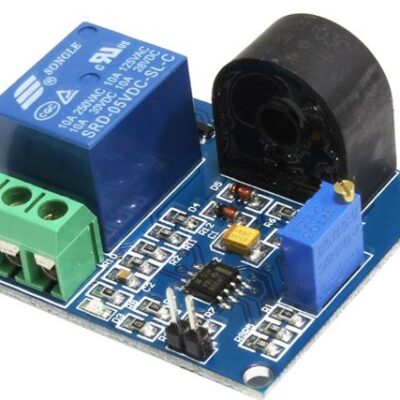
The AC protection switch can independently cut off the short circuit/current limiting protection module of the power supply line
(Test object: AC current, with real-time current detection, protection current range: 0.5A-20A)
Electrical parameters of this module:
DC power supply voltage: 9-24VDC;
Power supply current: 100mA-200mA;
Working temperature: -20 degrees ~ 125 degrees;
Isolation voltage: 1.5KV;
Current limit current range: 0.5A-20A
(1) When the actual current exceeds the current set by us, the relay can automatically disconnect the power supply line to protect the load.
(The actual current can be converted to the corresponding output voltage through the detection of the sensor, and then compared with the reference voltage)
How to set the current:
(2)
The current setting of the board is adjusted by the adjustable resistance on the board. (Highlights: This adjustable resistance can be freely rotated manually)
Unlock button:
(3)
The board has a small button, which can be set to lock and unlock.
Press the LOCK state: the relay is permanently locked;
It is in the Unlock state when it pops up: the relay will operate when it is over-current, but not when it is flowing.
Board size:
(3) 56mm*55mm with 4 M3 fixed mounting holes.
Shipping list:
(1) One AC current limiting protection module;
(2) One 4-color cable;
(3) An electronic file instruction manual;
Benefits of this module:
(4) It comes with a relay, which automatically cuts off the power supply line after overcurrent, and has a fast response time;
it can be set in two states, locked and unlocked, and the adjustable resistance can be manually rotated
Applications:
1) AC/DC current detection;
2) Motor stall/heat protection;
3) Leakage protection;
4) Real-time sampling of load current A/D
Detection principle
u First connect the single wire of the test object in series to the seat J4 of the board. After fixing it,
we supply power to the small board and also allow the testing equipment to start working normally. At the same time, press the lock button in the LOCK state.
u At this time, we refer to the CH1_Work indicator on the board. If the CH1_Work LED is off at this time, turn the adjustable resistor R17 toward the (+) arrow (clockwise). When the set value Vref is greater than the actual output voltage Vout1 , The LED marked CH1_Work turns from off to on. This is a critical point. At this time, the actual output voltage Vout1 of the sensor will be compared with the reference voltage Vref we set. When the load overcurrent, the actual output voltage exceeds the reference voltage, the single-chip can detect the overcurrent level signal in time, The low level will be output on the corresponding I/O port. At this time, the relay will act once (a tick will be heard), cut the power supply line, and play a role in timely protection.
u How to set the reference voltage is appropriate:
Here we focus on how to set the reference voltage to compare with the actual voltage;
There are 2 LED indicators on the board, we briefly describe the significance of its representation;
(1) CH1_Work LED indicator
u CH1_Work is on when the set reference voltage Vref> Vout (actual output voltage);
u CH1_Work is off when the set reference voltage Vref <Vout (actual output voltage);
Through the state of CH1_Work on or off, we can easily judge the size of the reference voltage at this time, so we can set the reference voltage we need;
Turn the (+) arrow (clockwise) to turn the adjustable resistor R17, Vref increases;
Turn the (-) arrow indication (counterclockwise) to turn the adjustable resistor R17, Vref decreases;
(2) Relay_led indicator
When the solid state relay is turned on, the Relay_led indicator lights;
When the solid state relay is not conducting, the Relay_led indicator is off.
(3) What role does the reset button Reset play?
Bounce the button to make it in the UNLOCK state. At this time, the board is in the unlocked state. Then,
if the detected device has an overcurrent, the relay will be in a repeated switching state (you will hear a ticking sound continuously).
Press the button to make it in the LOCK state, then if the detected device overcurrent occurs,
the relay will act once (only a ticking sound will be heard) to permanently disconnect the line;
if you want to unlock the lock state, you need to re-lock Bounce (press Reset), at this time, switch to UNLOCK state.
(4) No alarm when the tested equipment is working normally, how to set the “reference voltage” when the alarm exceeds the normal working current
First of all, after the board is powered on, the power device of the detected object will start working normally (at the same time, the key is lifted to make it in the unlocked state). Let us look at the state of the board CH1_Work at this time;
u If the CH1_Work LED is off at this time, we turn the adjustable resistor R17 according to the (+) arrow indication (clockwise) until CH1_Work is on. At this time, we must pay attention to the criticality of CH1_Work from off to on. The point is that the set reference voltage is close to the actual output voltage. At this time, the comparator has a pulse signal output. At this time, because it is in an unlocked state, the relay will switch repeatedly (you will hear a ticking sound continuously); Set the alarm when the normal operating current is exceeded. “We must increase the reference voltage slightly, and turn the adjustable resistor R17 toward the (+) arrow (clockwise), (the amount of increase needs to be adjusted by the customer according to the current setting. , In principle, just increase it a little, don’t over-tighten it. If the reference voltage deviates too far from the actual output voltage, the comparator has no pulse signal output.) After the setting is completed, (it must be noted that you must press Red button to make it in locked state), when the device is abnormal and exceeds the set operating current, the MCU can detect the overcurrent level signal in time and output a low level at the corresponding I/O port. At this time, the relay Action once (a tick will be heard), automatically locked in the protected state, cut the line.
u If the CH1_Work LED is on at this time, we turn the adjustable resistor R17 toward the (-) arrow indication (counterclockwise) until the CH1_Work is turned off. At this time, we must pay attention to this. The critical point is that the set reference voltage is close to the actual output voltage. At this time, the comparator has a pulse signal output. Because it is in an unlocked state, the relay will switch repeatedly (you will hear a ticking sound continuously); we still need to do One thing, turn the adjustable resistor R17 to the (+) arrow direction (counterclockwise), and turn the CH1_Work LED to the bright state; in order to set the alarm when the normal operating current is exceeded, we must increase the reference voltage slightly , Turn the adjustable resistor R17 toward the (+) arrow (clockwise), (the amount of increase needs to be adjusted by the customer according to the current set by him, in principle, increase it a little, don’t over-tighten it. If The reference voltage deviates too far from the actual output voltage, and the comparator has no pulse signal output.) After the setting is completed, (it must be noted that the red button must be pressed at this time to make it in the locked state). When the working current is fixed, the single-chip can detect the overcurrent level signal in time, and it will output a low level at the corresponding I/O port. At this time, the relay will act once (you will hear a tick), and it will automatically lock in the protection state. Cut the line.
Additional information
| Weight | 0.069 kg |
|---|
Brand
Chinese
Chinese

Chinese
You must be logged in to post a review.

3D Printer Extruder Cooling Heat Sink 40x40x11mm
EGP 45.000 exc. vat Add to cart
DIY LED Digital Electronic Watch
EGP 260.000 exc. vat Add to cart

M10 Nut for Threaded Rod Hex Nut 10mm
EGP 1.000 exc. vat Add to cart
Fast Blow Fuse 20mm Glass F5x20 0.315A
EGP 2.000 exc. vat Read more

Oscilloscope 20MHz Virtual USB | Hantek DSO-6022
EGP 3,600.000 exc. vat Read more
Refund Policy for UGE Electronics “Https://uge-one.com “
1. Returns and Refunds
Thank you for shopping at UGE Electronics “Https://uge-one.com “. If you are not entirely satisfied with your purchase, we’re here to help.
2. Eligibility for Refund
To be eligible for a refund, please make sure that:
– The item was purchased in the last 14 days.
– The item is in the original packaging.
– The item isn’t used or damaged.
3. How to Initiate a Refund
To initiate a refund, please contact our customer support at [[email protected]] or [01066552125]. Provide your order number and details about the product you would like to return.
4. Refund Processing Time
Once we receive your item, we will inspect it and notify you that we have received your returned item. We will immediately notify you on the status of your refund after inspecting the item.
If your return is approved, we will initiate a refund to your credit card (or original method of payment). You will receive the credit within a certain amount of days, depending on your card issuer’s policies.
5. Shipping Costs
Shipping costs are non-refundable. If you receive a refund, the cost of return shipping will be deducted from your refund.
6. Exchanges
If you wish to exchange an item, please contact our customer support. You will be responsible for the return shipping costs, and we will cover the shipping costs of the replacement item.
7. Damaged or Defective Items
If you received a damaged or defective product, please contact us immediately for assistance. We will work with you to resolve the issue promptly.
8. Contact Information
If you have any questions about our Refund Policy, please contact us at [[email protected]].
Important Note: This Return & Refund Policy is applied only for Orders invoiced VIA UGE Electronics, and regarding any Orders has been invoiced VIA any Other Vendor you can check the Return & Refund Policy of this Vendor VIA the Vendor Stroe Page, and it’s not our responsibility for any issue between you and the Vendor.
Product Enquiry
Related products
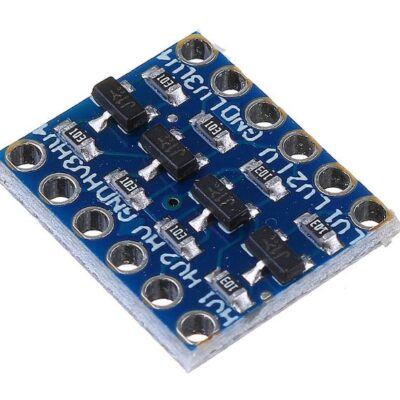
Bi-Directional 4-way level conversion module
EGP 25.000 exc. vat Add to cart
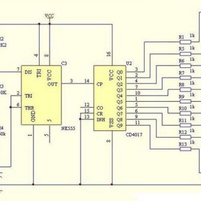
DIY Flasher Running Water Kit LM555 and CD4017
EGP 95.000 exc. vat Add to cart
Reviews
There are no reviews yet.