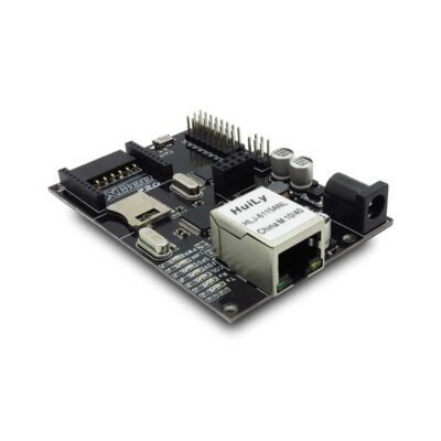
The Arduino Robot Controller Board is a unique Arduino board which features a L298P motor driver, an XBee socket, nRF24L01+ module interface, Micro SD socket and an ATMega32U4. The bootloader of Mboard is based on Arduino Leonardo. With motor driver chip L298P, this board can drive the DC motor directly and stepper motor with software IO control. This board will add wireless as well as motor control connectivity to your projects. It’s great for anything from home automation to robot control.
Spec
PCB size
80.77mm X 57.66mm X 1.6mm
Power supply
7~23V DC
POE supply
7~23V
Microprocessor
Atmega32u4
Indicators
PWR, Tx, Rx, D13, C1, C2, C3, C4
Communication Interface
XBee,nRF24L01+,UART,IIC
Electrical Characteristics
Specification
Min
Type
Max
Unit
Power Voltage
7
–
23
VDC
Input Voltage VH (Target Voltage = 3.3V)
3
3.3
3.6
V
Input Voltage VL:
-0.3
0
0.5
V
Current Consumption(Except Motor Drive Current)
–
100
500
mA
Peak Output Current(Every Channel)
-Non Repetitive(t=100us)
–
–
3
A
-Repetitive(80%on-20%off, ton=10ms)
–
–
2.5
A
-DC operation
–
–
3
A
Hardware
Top View Map
Pin map
ITDB02 EB Interface
Index of Interface
Name of Interface
Index of Arduino
Pin of Atmega32u4
1
EB0
A0
PF7
2
EB1
A1
PF6
3
EB2
A2
PF5
4
EB3
A3
PF4
5
EB4
A4
PF1
6
EB5
A5
PF0
nRF24L01+ Module Interface
Index of Interface
Name of Interface
Index of Arduino
Pin of Atmega32u4
1
GND
–
–
2
3V3
–
–
3
CE
D5
PC6
4
CS
D9
PB5
5
SCK
D15
PB1
6
MOSI
D16
PB2
7
MISO
D14
PB3
8
IRQ
D6
PD7
Micro SD Socket
Index of Interface
Name of Interface
Index of Arduino
Pin of Atmega32u4
1
SD_CS
D4
PD4
2
MOSI
D16
PB2
3
3V3
–
–
4
SCK
D15
PB1
5
GND
–
–
6
MISO
D14
PB3
Moto Drive Interface
Index of Interface
Name of Interface
Index of Arduino
Pin of Atmega32u4
1
IN1
D7
PE6
2
IN2
D8
PB4
3
IN3
D12
PD6
4
IN4
D13
PC7
5
ENA
D10(PWM)
PB6
6
ENB
D11(PWM)
PB7
XBee Communication Interface
Index of Interface
Name of Interface
Index of Arduino
Pin of Atmega32u4
1
RX
D0
PD2
2
TX
D1
PD3
Installation
Mboard can drive two DC motors at the same time. OUT1/OUT2 is completely symmetrical as OUT3/OUT4 on the board.
DC motor input has three pins, In1, In2 and EnA. In1 and In2 are digital ports which are used to control the direction of the motors, EnA is connecting with PWM port of control board to control the speed of motor.
EnA
In1
In2
LED Inductor
Description
0
X
X
<td style="border: 1px so
Additional information
Weight
0.025 kg
Brand
Chinese
Chinese
Chinese
Reviews
There are no reviews yet.
Be the first to review “Arduino Robot Controller (Arduino & L298 & SD & Xbee header)” Cancel reply









Reviews
There are no reviews yet.