Description
ESP32 Development Board For IOT Attendance Projects
All-in-One ESP32 Development Platform for IoT Applications
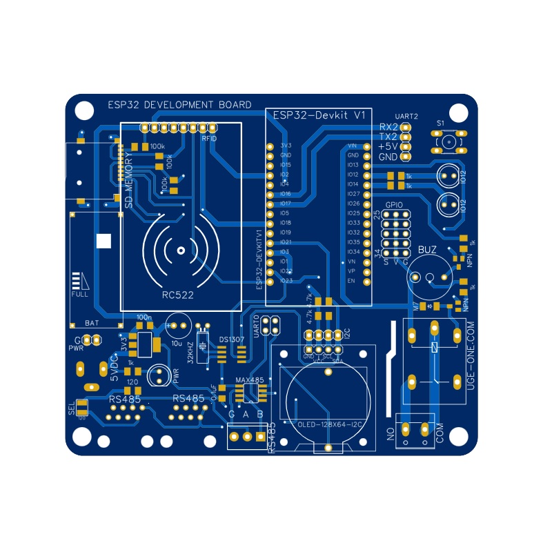
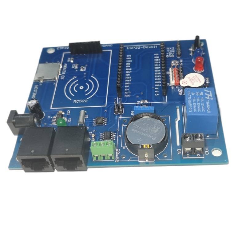
Kickstart your Internet of Things projects, especially attendance and access control systems, with this feature-packed ESP32 Development Board. Designed as a central hub, this board provides convenient sockets, headers, and onboard peripherals to seamlessly integrate a standard ESP32 Dev Kit module along with essential components like RFID readers, displays, and communication interfaces. Stop wrestling with messy breadboards and jump straight into development!
This board simplifies prototyping by bringing together common IoT hardware elements onto a single PCB. It includes dedicated headers for popular modules, robust communication options, user interface elements, and control capabilities, making it perfect for students, hobbyists, and developers building connected devices.
Key Features & Benefits:
-
ESP32 Dev Kit Socket: Standard headers to plug in your preferred ESP32 development module (e.g., ESP32-WROOM-32 based boards). Benefit: Leverage the powerful dual-core processor, Wi-Fi, and Bluetooth capabilities of the ESP32 easily.
-
RC522 RFID Module Header: Dedicated SPI header for connecting the popular MFRC522 RFID reader/writer module. Benefit: Quickly implement RFID-based identification for attendance, access, or tracking.
-
0.96″ OLED Display Header: I2C header ready for standard 0.96-inch SSD1306 OLED displays. Benefit: Add visual feedback, status updates, or user menus to your project effortlessly.
-
Onboard Relay: Integrated relay with screw terminals (connected to D13). Benefit: Directly control mains-powered devices or high-current DC loads like door locks, lights, or alarms safely.
-
DS1307 RTC & Battery Holder: Real-Time Clock chip with CR2032 battery backup. Benefit: Maintain accurate date and timekeeping even when the main power is off, crucial for logging and scheduling.
-
RS485 Interface: Onboard SP485 transceiver with auto-direction control (uses UART0) and both screw terminal & RJ45 connectors. Benefit: Implement robust, long-distance wired communication for industrial environments or multi-device networks.
-
SD Card Slot: Standard SD card socket (uses SPI). Benefit: Log large amounts of data, store configuration files, or serve web pages locally.
-
User Interface Elements: Includes two general-purpose LEDs (D12, D14), a push button (D26), and a buzzer (D27). Benefit: Provides immediate status indication and basic user interaction capabilities without extra wiring.
-
Convenient Powering: Standard DC barrel jack input (5V recommended) with onboard 3.3V regulation. Benefit: Easy and stable power supply for the entire board and connected modules.
-
GPIO Expansion Header: Breaks out unused ESP32 pins (D25, D33, D32, D35, D34). Benefit: Allows connection of additional sensors, actuators, or custom circuitry.
Important Note:
This product is the development board PCB with its onboard components (Relay, RTC, RS485 circuitry, SD slot, etc.) only. The ESP32 module, RC522 RFID module, and OLED display module are NOT included and must be purchased separately.
Ideal Use Cases:
-
IoT Based Attendance Systems
-
RFID Access Control Systems
-
Environmental Data Loggers
-
Home Automation Controllers
-
Industrial Monitoring Nodes
-
Educational Platform for Learning ESP32 and IoT peripherals
Specifications:
-
Main Processor Socket: Header for standard ESP32 Dev Kits (30 or 38 pin, check compatibility)
-
RFID Header: Pins for RC522 Module (SPI: D2, D18, D23, D19, D5)
-
OLED Header: Pins for 0.96″ I2C OLED (I2C: D22, D21)
-
RTC: DS1307 with CR2032 Holder (I2C: D22, D21)
-
RS485: SP485 Transceiver, Auto-Direction (UART0: TX0, RX0), RJ45 & Screw Terminals, Selectable 120Ω Termination
-
Storage: Micro SD Card Slot (SPI: D4, D23, D18, D19)
-
Relay: 5V Coil Relay (Load rating typically 10A/250VAC, 10A/30VDC – verify relay markings), Control Pin: D13
-
User I/O: LEDs (D12, D14), Button (D26 – use internal pull-up), Buzzer (D27)
-
Expansion: Header with D25, D33, D32, D35, D34
-
Power Input: DC Barrel Jack (5V Recommended)
Basic ESP32 Code Example (Blinking Onboard LED):
#define RED_LED_PIN 12
void setup() {
pinMode(RED_LED_PIN, OUTPUT);
Serial.begin(115200);
Serial.println("ESP32 Board LED Blink Example");
}
void loop() {
digitalWrite(RED_LED_PIN, HIGH);
Serial.println("Red LED ON");
delay(1000);
digitalWrite(RED_LED_PIN, LOW);
Serial.println("Red LED OFF");
delay(1000);
}
For More Products Like that Click Here
PCB For ESP32 RFID RTC RS485 SD Card built in Development Board










Emad Kamel –
انا طلبت عدد 2 وحدة من البورد واتمنى ان تكون امكانية لامدادى بعدد 2 من كل الاضافات المطلوب
2 esp 32
2 RFID reader
2 oled screen
وساقوم بدفع الثمن الإضافى المطلوب
عماد كمال
0106 502 5029