Description
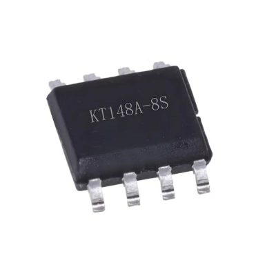
GP8102S-TC50-EW Digital PWM to Analog Signal Converter Chip SOP8
Here are the detailed specifications for the GP8102S-TC50-EW Digital PWM to Analog Signal Converter IC (SOP-8 package):
GP8102S-TC50-EW Key Specifications
Manufacturer: ChipHC (Chip-Hai Technology)
Package: SOP-8
Type: High-resolution PWM to voltage/current converter
1. Electrical Characteristics
-
Supply Voltage: 3.0V to 5.5V
-
PWM Input Frequency: 1Hz to 1MHz
-
Output Options:
-
Resolution: 16-bit effective (0.0015% FSR)
-
Linearity Error: ±0.1% FSR (typical)
-
Output Ripple: <10mV (typical)
-
Power Consumption: <3mA (operating)
2. Pinout (SOP-8)
3. Key Features
-
High Precision: 16-bit DAC equivalent performance
-
Wide PWM Frequency Range: 1Hz to 1MHz
-
Low Output Ripple: Built-in filtering
-
Multiple Output Ranges: Configurable via ADJ pin
-
Temperature Range: -40°C to +85°C
4. PWM to Voltage Conversion
0% duty cycle → 0V output
100% duty cycle → 5V output (default)
5. Typical Applications
-
LED dimming control
-
Motor speed control
-
Analog signal generation from microcontrollers
-
Industrial process control (4–20mA loops)
-
Voltage-controlled oscillators (VCOs)
6. External Components Required
-
Power Supply: 3.3V or 5V stable supply
-
Filter Capacitor: 1µF–10µF on VCC pin
-
Output Filter: 0.1µF ceramic capacitor on VOUT
Arduino Example Code
// Generate PWM for GP8102S (0-5V output)
const int pwmPin = 9; // Arduino PWM pin
void setup() {
pinMode(pwmPin, OUTPUT);
// Set PWM frequency to ~1kHz (compatible with GP8102S)
analogWriteFrequency(pwmPin, 1000);
}
void setVoltage(float voltage) {
// Convert voltage (0-5V) to PWM duty cycle (0-255)
int duty = map(voltage * 100, 0, 500, 0, 255);
analogWrite(pwmPin, duty);
}
void loop() {
setVoltage(2.5); // Output 2.5V
delay(1000);
setVoltage(5.0); // Output 5.0V
delay(1000);
}
Configuration Options
-
0–5V Output (default): Connect ADJ pin to GND
-
0–10V Output: Use external voltage divider on ADJ pin
-
Current Output: Add NPN transistor and sense resistor
Performance Characteristics
-
Setting Time: <10ms (to within 1% of final value)
-
Temperature Coefficient: ±50ppm/°C
-
Long-Term Stability: ±0.05% per 1000 hours
Advantages over Traditional PWM+RC Filter
✅ Higher precision (16-bit vs 8–10 bit)
✅ Lower output ripple (active filtering)
✅ Faster response (digital calibration)
✅ Smaller footprint (SOP-8 vs discrete components)








Reviews
There are no reviews yet.