No products in the cart.

Simple FM wireless microphone transmitter module electronic DIY Kit
Out of stock
EGP 35.000 exc. vat
Out of stock
Brand:Chinese
Description
The transmission frequency of this circuit is about 90MHz. The receiving equipment uses a common FM radio. Adjust the inductance L to adjust the transmission frequency to avoid the local radio station. The working voltage of the circuit: DC 3V-6V. The transmission distance of this kit is about ten to several tens Meters, the transmission distance is related to the power supply voltage, antenna length matching and impedance matching, regional openness, electromagnetic wave interference, and receiving equipment sensitivity.
1. Performance parameters
Frequency range: 80MHz—108MHz
Working voltage: DC3V—6V
Second, the circuit description

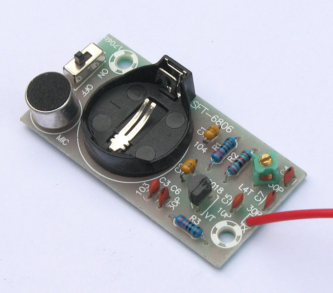
MIC is an electret microphone. Its function is to sense the weak vibration of sound waves in the air and output the same electrical signal as the sound changes. This site uses a microphone with higher sensitivity, which can generally output an audio signal of more than tens of millivolts, which is enough to modulate the frequency of the next-level high-frequency oscillation signal. Note: The microphone has positive and negative poles, and the negative pole is generally connected to the case.
R1 is the bias resistance of the MIC electret microphone. With this resistance, the microphone can output audio signals. This is because the MIC microphone itself has a pole field effect tube amplifier circuit for impedance matching and improving output capabilities.
C2 is an audio signal coupling capacitor, which delivers the sound electrical signal output by the microphone to the next level.
C2 is the base filter capacitor of Q9018. On the one hand, it filters out high-frequency noise. On the other hand, the high-frequency potential of Q9018 is 0. For high-frequency circuits above 50MHz, Q9018 is a common base amplifier circuit. This is Finally, it can form the basis of oscillation. Because the basic condition of the oscillating circuit is that it must have a certain gain, and then it has feedback with a suitable phase (generally positive feedback).
R2 is the base bias resistor of Q9018, providing Q with a smaller base current, and Q will have a larger emitter current through R3. Because the current action in R2 and R3 will produce a voltage drop on their respective resistances and affect each other, the result will automatically stabilize at a certain value state, which is the emitter follower mentioned in the book.
R3 is the emitter resistance of Q9018, which serves to stabilize the DC operating point, and C6 also constitutes the role of high-frequency signal load resistance, which is also part of the entire high-frequency oscillation circuit.
C4 and L form a parallel resonant circuit, which plays the main role of selecting the oscillation frequency. Changing the capacity of C4 or changing the shape of L (including the number of turns) can easily change the transmission frequency.
C7 is a high-frequency signal output coupling capacitor, the purpose is to make the high-frequency signal into radio waves and radiate into the sky. Therefore, the antenna is best to be straight up, and the length is preferably equal to the radio wave frequency wavelength (or an integer multiple), and the surroundings should be wide open, without being blocked by metal objects. Note: The wavelength is equal to the reciprocal of the frequency. When the frequency changes, the wavelength will also change. Furthermore, the specific length of the antenna is also related to the output impedance of the circuit, the thickness of the antenna, etc. In amateur situations, just connect a piece of wire. (If you want to pursue the longest launch distance, you can try more in this area. The component package of this site has been tested by the technical staff of this site, and the effect can easily reach 50 meters away.)
C5 is the feedback capacitor, and the circuit starts to oscillate The key component is it. When analyzing the high-frequency state of this circuit, the collector is the output and the emitter is the input. The output signal is added to the input through C5, which generates strong positive feedback and naturally generates oscillation. This is actually the capacitive three-point oscillation circuit mentioned in the book.
C1 is the power supply filter capacitor, which provides a loop for the AC signal and reduces the AC internal resistance of the power supply.
TX connects to the antenna : a piece of wire can be connected as an antenna, the antenna should not be too long, so as not to affect frequency stability
Component list :
|
Tag |
name |
specification |
Quantity |
|
R1 |
resistance |
2.2k |
1 |
|
R2 |
resistance |
22k |
1 |
|
R3 |
resistance |
220 |
1 |
|
C1 , C2 |
Ceramic capacitor |
104 |
3 |
|
C3 |
Ceramic capacitor |
103 |
1 |
|
C6 , C7, C4 |
Ceramic capacitor |
30 |
3 |
|
C5 |
Ceramic capacitor |
10 |
1 |
|
Q |
Triode |
9018 |
1 |
|
L |
inductance |
4T |
1 |
|
MIC |
Electret microphone |
|
1 |
|
BT3V |
CR2032 battery holder |
3v |
1 |
|
|
PCB board |
26*52mm |
1 |
|
Instructions |
|
|
1 |
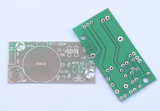
The following is the actual product
1. PCB empty board, without parts
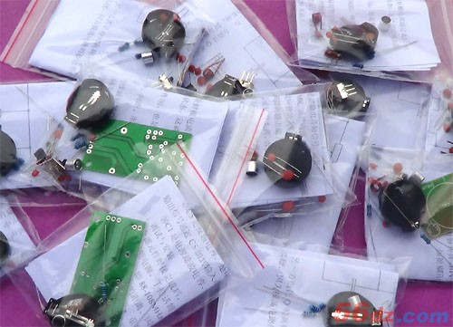
2. Kit parts, assembled by yourself
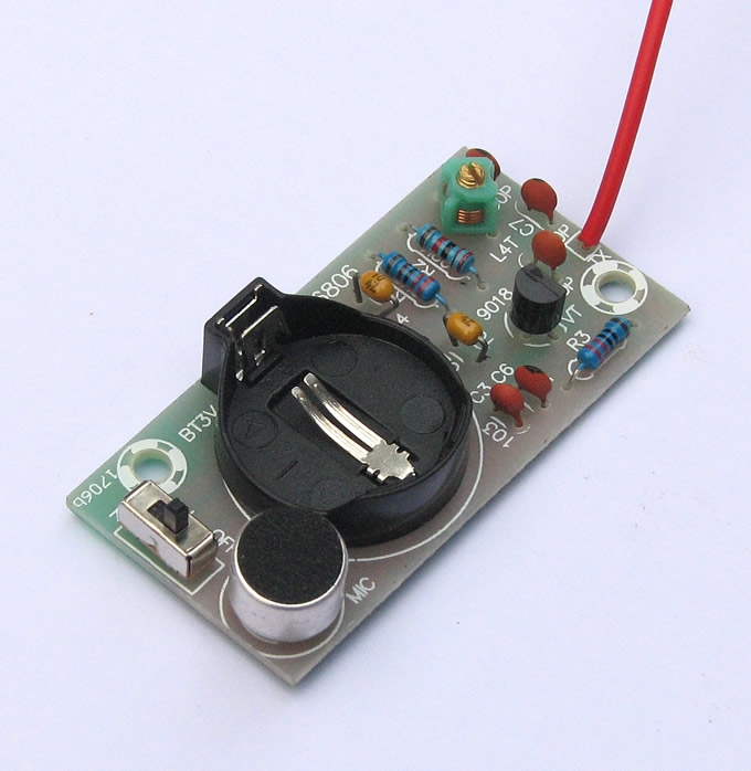
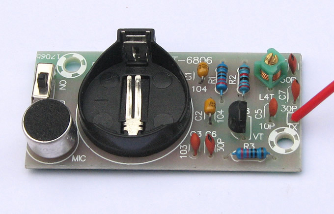
Welded finished product
debugging:
Connect the power supply and antenna test, the antenna can use 20-40 cm thick wire (the antenna should not be too long, so as not to affect the frequency stability ), not provided in the kit, you need to bring your own. The receiving equipment uses FM radio to adjust the tightness of the inductive coil on the simple wireless microphone, so that the radio can receive the signal of the microphone.
Additional information
| Weight | 0.032 kg |
|---|
Brand
Chinese
Chinese

Chinese
You must be logged in to post a review.
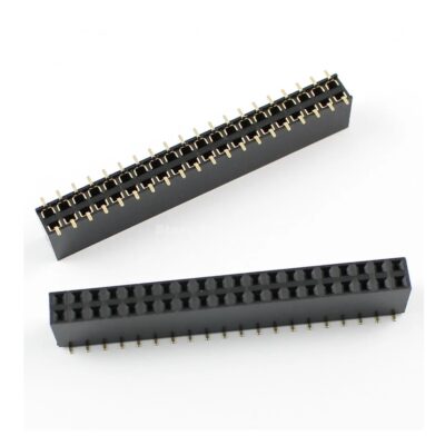
SMD Pin Header Female 2X20 Connector 2.54mm pitch
EGP 16.000 exc. vat Add to cart
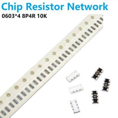
0603 SMD Resistor Network Exclusion 8P4R 10K 8Pin
EGP 2.000 exc. vat Add to cart
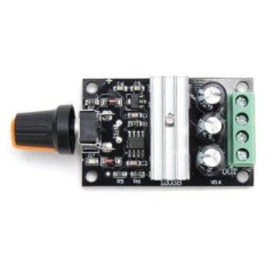
PWM DC motor speed controller Driver 3A (6V-28V) Duty Cycle (0-100%)
EGP 90.000 exc. vat Read more
Fuse 30mm Glass
EGP 0.000 – EGP 0.500 exc. vat Select options
TT6061A AC 3 STEPS TOUCH-DIMMER Controller DIP8
EGP 30.000 exc. vat Add to cart
AT24C256 I2C INTERFACE EEPROM MEMORY MODULE
EGP 25.000 exc. vat Read more
Refund Policy for UGE Electronics “Https://uge-one.com “
1. Returns and Refunds
Thank you for shopping at UGE Electronics “Https://uge-one.com “. If you are not entirely satisfied with your purchase, we’re here to help.
2. Eligibility for Refund
To be eligible for a refund, please make sure that:
– The item was purchased in the last 14 days.
– The item is in the original packaging.
– The item isn’t used or damaged.
3. How to Initiate a Refund
To initiate a refund, please contact our customer support at [[email protected]] or [01066552125]. Provide your order number and details about the product you would like to return.
4. Refund Processing Time
Once we receive your item, we will inspect it and notify you that we have received your returned item. We will immediately notify you on the status of your refund after inspecting the item.
If your return is approved, we will initiate a refund to your credit card (or original method of payment). You will receive the credit within a certain amount of days, depending on your card issuer’s policies.
5. Shipping Costs
Shipping costs are non-refundable. If you receive a refund, the cost of return shipping will be deducted from your refund.
6. Exchanges
If you wish to exchange an item, please contact our customer support. You will be responsible for the return shipping costs, and we will cover the shipping costs of the replacement item.
7. Damaged or Defective Items
If you received a damaged or defective product, please contact us immediately for assistance. We will work with you to resolve the issue promptly.
8. Contact Information
If you have any questions about our Refund Policy, please contact us at [[email protected]].
Important Note: This Return & Refund Policy is applied only for Orders invoiced VIA UGE Electronics, and regarding any Orders has been invoiced VIA any Other Vendor you can check the Return & Refund Policy of this Vendor VIA the Vendor Stroe Page, and it’s not our responsibility for any issue between you and the Vendor.
Product Enquiry
Related products
HC595 LCD Serial Interface Module
EGP 35.000 exc. vat Add to cart
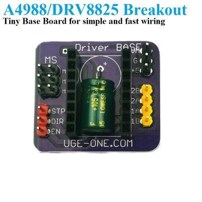
Tiny A4988 DRV8825 Extension Driver Board for Stepper Motor Nema17
EGP 50.000 exc. vat Add to cart
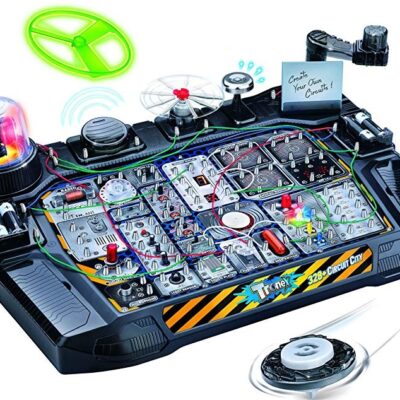
STEM Toys Circuit Lab Electronics Exploration Kit 328 in 1 STEAM Projects
EGP 3,900.000 exc. vat Add to cart
Reviews
There are no reviews yet.