Description
Overview
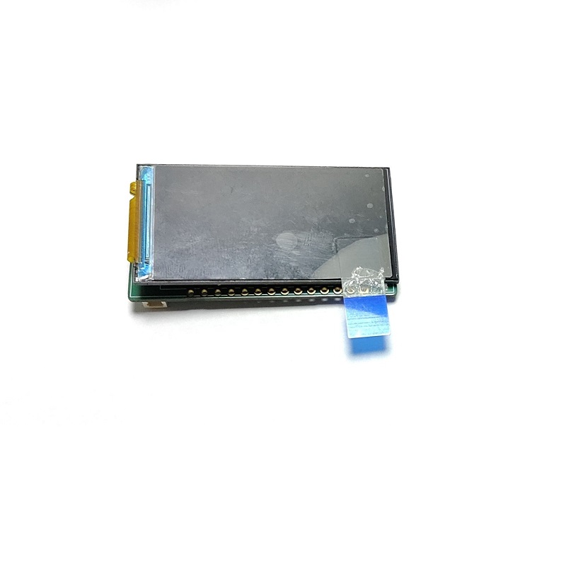
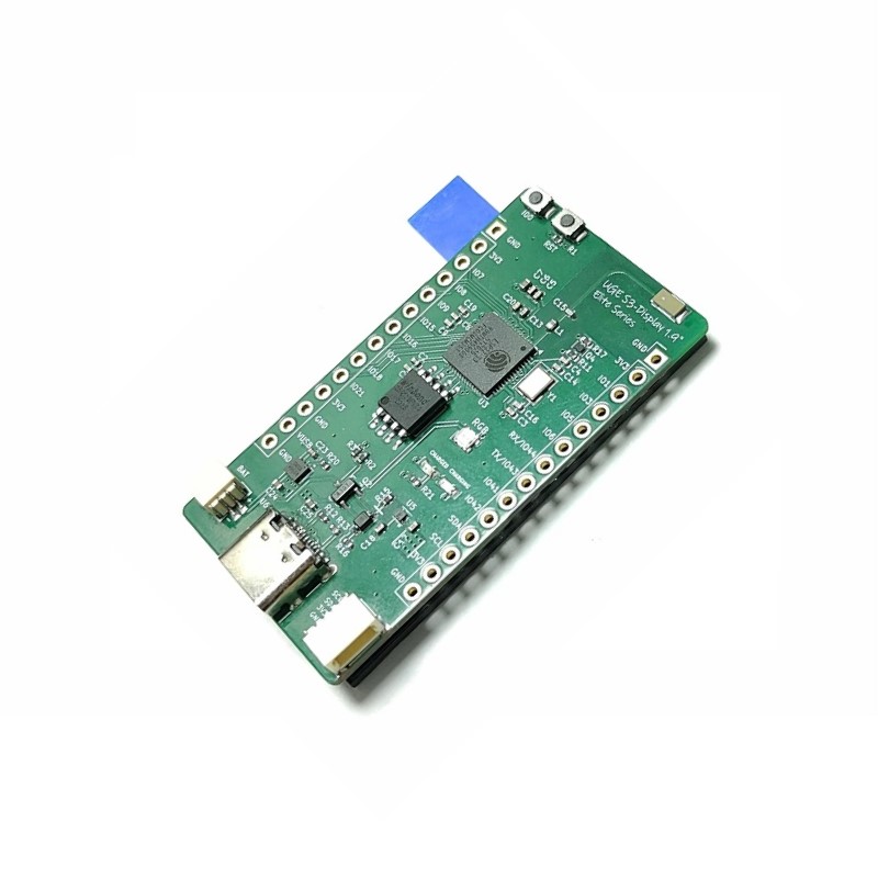
The UGE S3-Display 1.9″ Elite Series is a compact, powerful development board built around the ESP32-S3 wireless MCU. It features a 1.9-inch 170×320 IPS LCD driven by the ST7789 over SPI, 16 MB Flash, and 8 MB OPI PSRAM for demanding UI and IoT work.
USB-C, LiPo charging, battery voltage sensing, RGB LED feedback, and a STEMMA QT / I²C connector make it a strong fit for portable projects, UI prototypes, and wireless devices.
Highlights
1.9″ ST7789 LCD
170×320 IPS display over a 4-wire SPI interface.
LiPo charging
On-board TP4056 charger with charging and charged status LEDs.
Battery ADC
Battery voltage sensing on GPIO4 through a VBAT/3 divider.
STEMMA QT / I²C
Easy expansion for sensors and peripherals over a standard STEMMA QT / Qwiic connector.
Key features
- ESP32-S3 wireless MCU (Wi-Fi + Bluetooth LE 5)
- 16 MB Flash + 8 MB OPI PSRAM
- 1.9″ 170×320 IPS LCD
- ST7789 driver, SPI interface
- Non-touch display
- USB-C for power and programming
- TP4056 LiPo charging
- Battery voltage sensing on GPIO4 (VBAT/3, 200 kΩ / 100 kΩ)
- On-board WS2812B RGB LED on GPIO46
- BOOT and RESET buttons
- STEMMA QT / Qwiic I²C connector
Technical specifications
Display interface (ST7789)
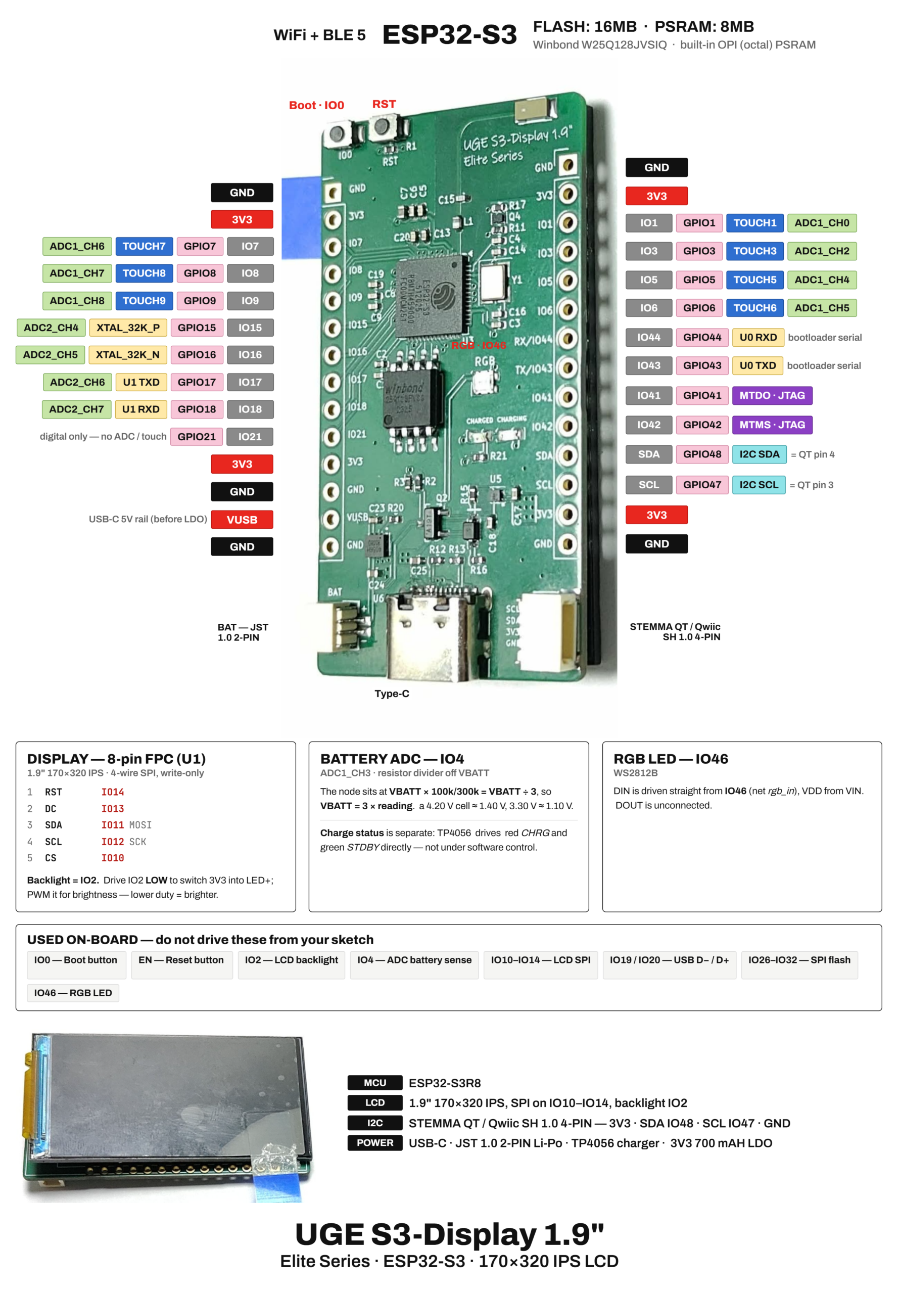
Backlight note: drive GPIO2 LOW to turn the backlight on. PWM is supported; a lower duty cycle makes the display brighter.
Display init notes for firmware: panel 170×320, offset_x = 35, color invert enabled, SPI write-only.
Header pinout
Left header (top → bottom)
BOOT (IO0), RST, GND, 3V3, IO7, IO8, IO9, IO15, IO16, IO17, IO18, IO21, 3V3, GND, VUSB, GND, BAT (JST 1.0 2-pin)
Right header (top → bottom)
GND, 3V3, IO1, IO3, IO5, IO6, IO44 (U0 RXD), IO43 (U0 TXD), IO41, IO42, IO48 (I²C SDA), IO47 (I²C SCL), 3V3, GND, STEMMA QT / Qwiic
STEMMA QT / Qwiic
3V3 · SDA GPIO48 · SCL GPIO47 · GND
Power and battery
- USB-C is used for power and programming.
- LiPo charging is handled by TP4056. Red LED = charging, green LED = charged / standby. These LEDs are hardware-driven, not software-controlled.
- Battery voltage is read on GPIO4 through a VBAT/3 divider.
VBAT = 3 × ADC reading
Example: 4.20 V cell → 1.40 V at GPIO4; 3.30 V cell → 1.10 V.
- 3.3 V is supplied by a 700 mA LDO. VUSB is the USB-C 5 V rail before the regulator.
Pins used on-board (do not drive from user firmware)
Ideal for
Portable IoT devices, UI prototypes, status displays, wireless dashboards, and compact battery-powered projects that need a built-in screen without extra wiring.
Sample Test Code For Arduino
check this file as a basic and fast test code








Reviews
There are no reviews yet.