Description
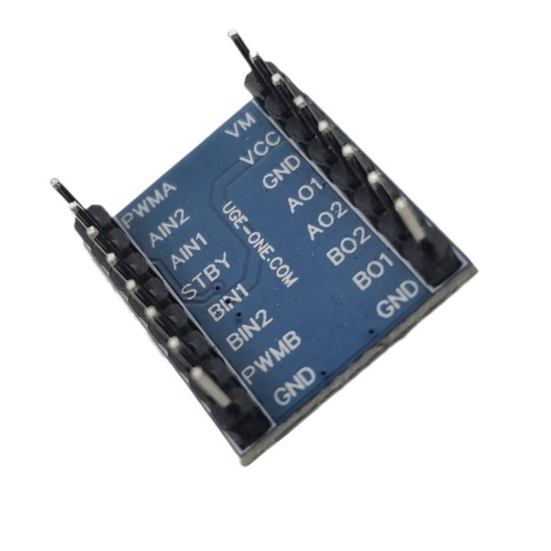
TB6612FNG Dual DC Motor Driver
Description: The TB6612FNG motor driver can control up to two DC motors at a constant current of 1.2A (3.2A peak). Two input signals (IN1 and IN2) can be used to control the motor in one of four function modes – CW, CCW, short-brake, and stop. The two motor outputs (A and B) can be separately controlled, the speed of each motor is controlled via a PWM input signal with a frequency up to 100kHz. The STBY pin should be pulled high to take the motor out of standby mode.
Logic supply voltage (VCC) can be in the range of 2.7-5.5VDC, while the motor supply (VM) is limited to a maximum voltage of 15VDC. The output current is rated up to 1.2A per channel (or up to 3.2A for a short, single pulse).
Board comes with all components installed as shown. Decoupling capacitors are included on both supply lines. All pins of the TB6612FNG are broken out to two 0.1″ pitch headers; the pins are arranged such that input pins are on one side and output pins are on the other.
Features:
- Power supply voltage: VM=15V max, VCC=2.7-5.5V
- Output current: Iout=1.2A(average) / 3.2A (peak)
- Standby control to save power
- CW/CCW/short brake/stop motor control modes
- Built-in thermal shutdown circuit and low voltage detecting circuit
- All pins of the TB6612FNG broken out to 0.1″ spaced pins
- Filtering capacitors on both supply lines
Dimensions: 0.8×0.8″
Each pin and its function is covered in the table below.
| Pin Label |
Function |
Power/Input/Output |
Notes |
| VM |
Motor Voltage |
Power |
This is where you provide power for the motors (2.2V to 13.5V) |
| VCC |
Logic Voltage |
Power |
This is the voltage to power the chip and talk to the microcontroller (2.7V to 5.5V) |
| GND |
Ground |
Power |
Common Ground for both motor voltage and logic voltage (all GND pins are connected) |
| STBY |
Standby |
Input |
Allows the H-bridges to work when high (has a pulldown resistor so it must actively pulled high) |
| AIN1/BIN1 |
Input 1 for channels A/B |
Input |
One of the two inputs that determines the direction. |
| AIN2/BIN2 |
Input 2 for channels A/B |
Input |
One of the two inputs that determines the direction. |
| PWMA/PWMB |
PWM input for channels A/B |
Input |
PWM input that controls the speed |
| A01/B01 |
Output 1 for channels A/B |
Output |
One of the two outputs to connect the motor |
| A02/B02 |
Output 2 for channels A/B |
Output |
One of the two outputs to connect the motor |
Now, for a quick overview of how to control each of the channels. If you are using an Arduino, don’t worry about this too much as the library takes care of all of this for you. If you are using a different control platform, pay attention. When the outputs are set to High/Low your motor will run. When they are set to Low/High the motor will run in the opposite direction. In both cases, the speed is controlled by the PWM input.
| In1 |
In2 |
PWM |
Out1 |
Out2 |
Mode |
| H |
H |
H/L |
L |
L |
Short brake |
| L |
H |
H |
L |
H |
CCW |
| L |
H |
L |
L |
L |
Short brake |
| H |
L |
H |
H |
L |
CW |
| H |
L |
L |
L |
L |
Short brake |
| L |
L |
H |
OFF |
OFF |
Stop |
Don’t forget STBY must be high for the motors to drive.









Reviews
There are no reviews yet.