Description
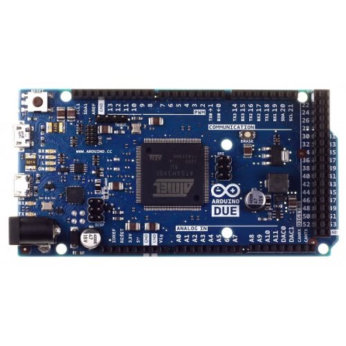
The Arduino Due is a microcontroller board based on the Atmel SAM3X8E ARM Cortex-M3 CPU (datasheet). It is the first Arduino board based on a 32-bit ARM core microcontroller. It has 54 digital input/output pins (of which 12 can be used as PWM outputs), 12 analog inputs, 4 UARTs (hardware serial ports), an 84MHz clock, a USB OTG capable connection, 2 DAC (digital to analog), 2 TWI, a power jack, an SPI header, a JTAG header, a reset button and an erase button.
Warning: Unlike other Arduino boards, the Arduino Due board runs at 3.3V. The maximum voltage that the I/O pins can tolerate is 3.3V. Providing higher voltages, like 5V to an I/O pin could damage the board.
The board contains everything needed to support the microcontroller; simply connect it to a computer with a micro-USB cable or power it with a AC-to-DC adapter or battery to get started. The Due is compatible with all Arduino shields that work at 3.3V and are compliant with the 1.0 Arduino pinout.
The Due follows the 1.0 pinout:
- TWI: SDA and SCL pins that are near to the AREF pin.
- The IOREF pin which allows an attached shield with the proper configuration to adapt to the voltage provided by the board. This enables shield compatibility with a 3.3V board like the Due and AVR-based boards which operate at 5V.
- An unconnected pin, reserved for future use.
The Due has a dedicated forum for discussing the board.
Summary
| Microcontroller |
|
AT91SAM3X8E |
| Operating Voltage |
|
3.3V |
| Input Voltage (recommended) |
|
7-12V |
| Input Voltage (limits) |
|
6-20V |
| Digital I/O Pins |
|
54 (of which 12 provide PWM output) |
| Analog Input Pins |
|
12 |
| Analog Outputs Pins |
|
2 (DAC) |
| Total DC Output Current on all I/O lines |
|
130 mA |
| DC Current for 3.3V Pin |
|
800 mA |
| DC Current for 5V Pin |
|
800 mA |
| Flash Memory |
|
512 KB all available for the user applications |
| SRAM |
|
96 KB (two banks: 64KB and 32KB) |
| Clock Speed |
|
84 MHz |
ARM Core benefits
The Due has a 32-bit ARM core that can outperform typical 8-bit microcontroller boards. The most significant differences are:
- A 32-bit core, that allows operations on 4 byte wide data within a single CPU clock.
- CPU Clock at 84Mhz.
- 96 KBytes of SRAM.
- 512 KBytes of Flash memory for code.
- a DMA controller, that can relieve the CPU from doing memory intensive tasks.
Power
The Arduino Due can be powered via the USB connector or with an external power supply. The power source is selected automatically.
External (non-USB) power can come either from an AC-to-DC adapter (wall-wart) or battery. The adapter can be connected by plugging a 2.1mm center-positive plug into the board's power jack. Leads from a battery can be inserted in the Gnd and Vin pin headers of the POWER connector.
The board can operate on an external supply of 6 to 20 volts. If supplied with less than 7V, however, the 5V pin may supply less than five volts and the board may be unstable. If using more than 12V, the voltage regulator may overheat and damage the board. The recommended range is 7 to 12 volts.









Reviews
There are no reviews yet.