Description
Overview
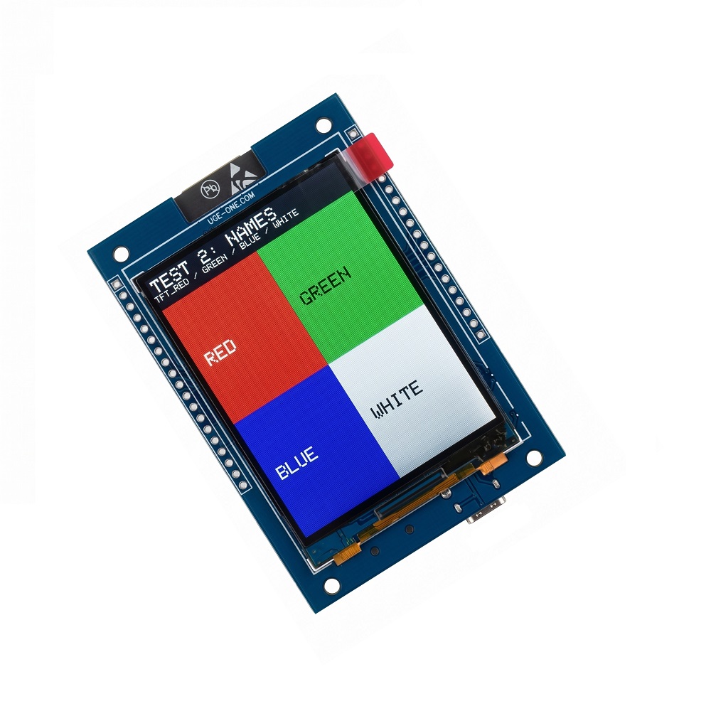
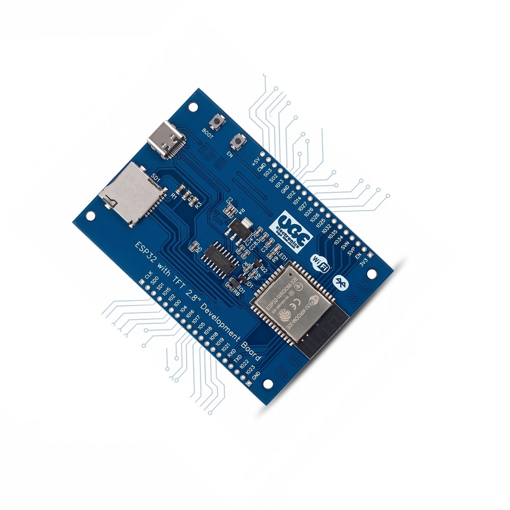
The UGE ESP32 2.8″ TFT Development Board is an ESP32-based development platform with a built-in 2.8-inch ST7789 320×240 SPI TFT display, microSD card interface, and USB-C programming interface.
The board integrates a CH340C USB-to-UART programming circuit and an AMS1117-3.3V regulator, allowing the board to be powered directly from a 5V supply while providing regulated 3.3V power for the ESP32, TFT display and microSD card.
Unlike compact ESP32 boards with limited accessible I/O, this board brings the available ESP32 GPIOs to edge-mounted headers, following the familiar arrangement of a 38-pin ESP32 development board. This allows the integrated display and SD card to be used while still providing GPIO access for additional sensors, modules, peripherals and custom hardware.
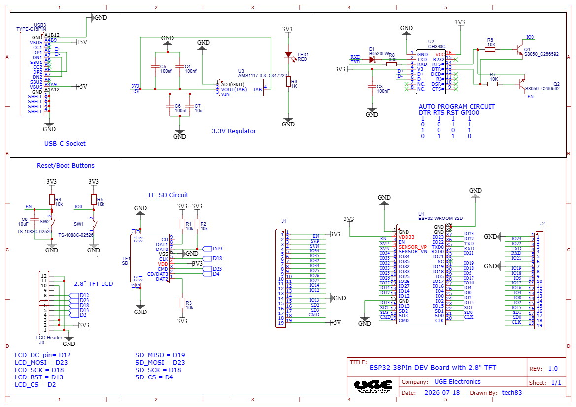
The TFT and microSD card share the same SPI bus, with separate chip-select signals, allowing both peripherals to operate efficiently using the ESP32’s hardware SPI interface. ESP32 documentation identifies GPIO18, GPIO19 and GPIO23 as the conventional VSPI clock, MISO and MOSI signals respectively.
Documentation & Resources
Hardware design Schematic, pinout, setup instructions, TFT_eSPI configuration, example code:
GitHub Repository – UGE ESP32 2.8″ TFT Development Board
Key Features
- ESP32 development board
- Integrated 2.8-inch ST7789 320×240 TFT display
- Integrated microSD card slot
- USB Type-C programming interface
- On-board CH340C USB-to-UART converter
- Automatic serial programming support
- 5V power input
- On-board AMS1117-3.3V regulator
- 3.3V power supplied to:
- ESP32
- TFT display
- microSD card
- ESP32 GPIOs brought out to edge headers
- GPIO arrangement designed to be familiar to users of 38-pin ESP32 development boards
- TFT and SD card share the same SPI bus
- Separate chip-select lines for TFT and SD
- Suitable for Arduino IDE and ESP32 development
- Suitable for graphical HMI and IoT applications
Display
Display Controller: ST7789
Display Size: 2.8 inch 320×240
Interface: SPI
Color: RGB TFT
Touch: Not specified
TFT Pin Assignment
Typical Arduino/TFT_eSPI configuration:
GPIO18 and GPIO23 are also the standard VSPI clock and MOSI signals on the ESP32, making them suitable for the shared SPI architecture.
microSD Card
The board includes an integrated microSD card connector for local storage.
The SD card uses the same SPI bus as the TFT display, while using an independent chip-select signal.
SD Pin Assignment
This means the TFT and SD card can share:
while using separate chip-select signals:
This is a standard and efficient way to connect multiple SPI peripherals to the ESP32.
Example Arduino Configuration
USB Programming
The board incorporates a CH340C USB-to-UART converter for programming and serial communication with the ESP32.
USB Features
- USB Type-C connector
- CH340C USB-to-UART converter
- ESP32 UART programming interface
- Serial monitor support
- USB-powered operation
- No external USB-to-UART programmer required
The board therefore provides a conventional development-board workflow:
PC → USB-C → CH340C → ESP32
Power Supply
Input
5V DC
The onboard AMS1117-3.3V linear regulator converts the 5V input to 3.3V for the board’s 3.3V circuitry.
3.3V Loads
The regulated 3.3V rail supplies:
- ESP32
- ST7789 TFT
- microSD card
- Associated logic circuitry
The 5V input should be applied to the board’s designated 5V power input/USB supply.
Important: The AMS1117 is a linear regulator, so its power dissipation depends on the total 3.3V load and input voltage.
GPIO Expansion
One of the main advantages of your design is that the integrated peripherals don’t consume the entire expansion interface.
The ESP32 GPIOs are brought to the long edge headers, allowing the board to be expanded with:
- Sensors
- Relays
- Motor drivers
- I²C modules
- UART devices
- SPI peripherals
- ADC sensors
- LEDs
- Buttons
- Automation modules
- Custom circuits
This makes the board useful as a general-purpose ESP32 development platform rather than a display-only controller.
ESP32 DevKit boards similarly expose GPIOs such as GPIO23, GPIO22, GPIO19, GPIO18, GPIO5, GPIO4, GPIO2, GPIO15, GPIO13 and GPIO12 on their headers.
Important GPIO Allocation
The following GPIOs are already assigned to the integrated peripherals:
| GPIO |
Function |
| GPIO23 |
TFT MOSI / SD MOSI |
| GPIO18 |
TFT SCLK / SD SCLK |
| GPIO19 |
SD MISO |
| GPIO2 |
TFT CS |
| GPIO4 |
SD CS |
| GPIO12 |
TFT DC |
| GPIO13 |
TFT RESET |
Therefore, these pins are not completely free GPIOs when using the onboard TFT and SD card.
The remaining exposed GPIOs can be used for user expansion according to the ESP32’s peripheral capabilities.
Technical Specifications
MCU: ESP32
Wireless: 2.4 GHz Wi-Fi + Bluetooth
Display: 2.8″ ST7789 TFT 320×240
Display Interface: SPI
Storage: microSD card
SD Interface: SPI
USB Interface: USB Type-C
USB-UART: CH340C
Programming: USB serial bootloader
Input Voltage: 5V DC
3.3V Regulator: AMS1117-3.3
TFT MOSI: GPIO23
TFT SCLK: GPIO18
TFT CS: GPIO2
TFT DC: GPIO12
TFT RST: GPIO13
SD MISO: GPIO19
SD MOSI: GPIO23
SD SCLK: GPIO18
SD CS: GPIO4
Expansion: ESP32 GPIO edge headers
Board Type: ESP32 development board
Software Compatibility
The board is suitable for development using:
- Arduino IDE
- ESP32 Arduino Core
- ESP-IDF
- PlatformIO
- TFT_eSPI
- Adafruit GFX-compatible display libraries
- Arduino SD / SD libraries
- Custom ESP32 firmware
For TFT_eSPI, the board can use:
Applications
- ESP32 HMI projects
- IoT controllers
- Smart-home controllers
- Data loggers
- Portable instruments
- Industrial monitoring
- Sensor dashboards
- Touch/display projects
- Graphical control panels
- SD-card data logging
- Wi-Fi monitoring systems
- Bluetooth projects
- Embedded GUI development
- ESP32 automation systems
- Custom handheld instruments
What’s Included
- 1 × UGE ESP32 2.8″ TFT Development Board
- Integrated ESP32 module
- Integrated 2.8″ ST7789 TFT
- Integrated microSD card connector
- Integrated CH340C USB-to-UART circuit
- Integrated AMS1117-3.3V regulator
microSD card is not included unless specifically stated.








Reviews
There are no reviews yet.