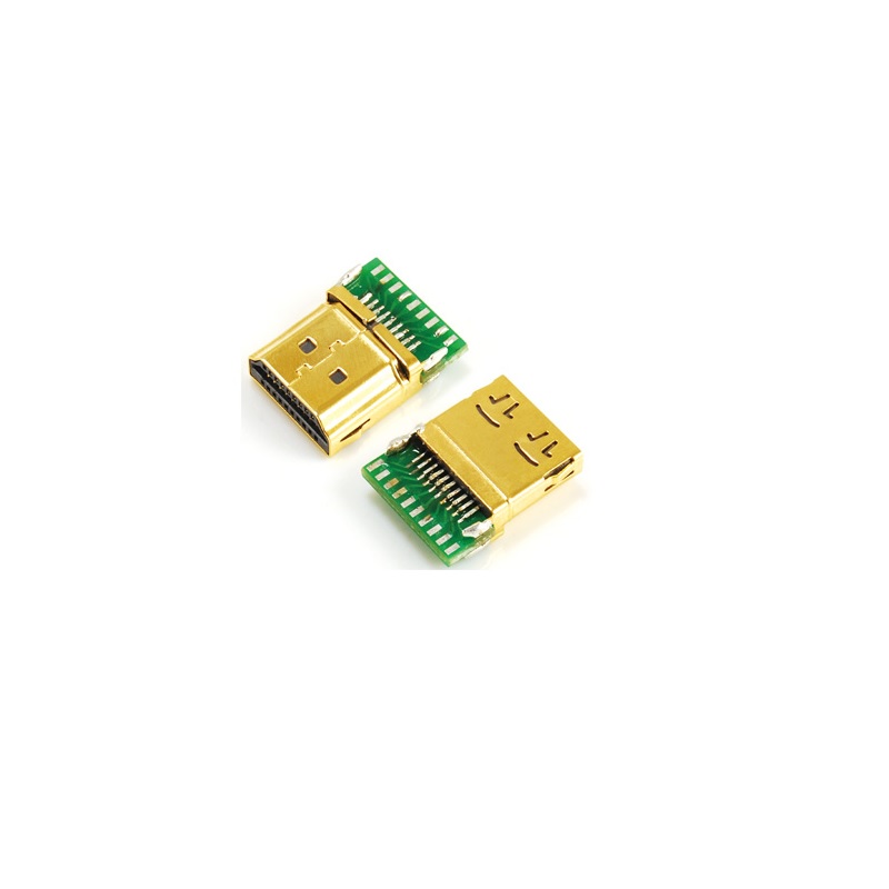
19-pin HDMI Type A Male Connector designed for PCB mounting with a solder termination. This is a standard component for integrating HDMI ports directly onto a circuit board.
| Parameter | Value |
|---|---|
| Connector Type | HDMI Type A (Standard HDMI) |
| Gender | Male (Plug) |
| Number of Contacts | 19 |
| Mounting Type | PCB Through-Hole |
| Orientation | 180° (Straight) or Right Angle, depending on exact variant |
| Termination Method | Solder |
| Rated Current | 0.5A Max |
| Rated Voltage | 40V Max |
| Contact Plating | Gold |
| Housing Material | PBT or ABS (UL94V-0 Flammability Rating) |
| Operating Temperature | -25°C to +85°C |
| Bandwidth | Supports data rates up to 10.8 Gbps (for HDMI 1.3) |
The 19 pins of an HDMI Type A connector are arranged in two staggered rows. The pin functions are grouped into high-speed video/audio channels and control lines .
| Pin | Signal |
|---|---|
| 1 | TMDS Data 2+ |
| 2 | TMDS Data 2 Shield |
| 3 | TMDS Data 2- |
| 4 | TMDS Data 1+ |
| 5 | TMDS Data 1 Shield |
| 6 | TMDS Data 1- |
| 7 | TMDS Data 0+ |
| 8 | TMDS Data 0 Shield |
| 9 | TMDS Data 0- |
| 10 | TMDS Clock+ |
| 11 | TMDS Clock Shield |
| 12 | TMDS Clock- |
| 13 | CEC (Consumer Electronics Control) |
| 14 | Reserved (N.C. on device) |
| 15 | SCL (DDC Clock / I²C) |
| 16 | SDA (DDC Data / I²C) |
| 17 | DDC / CEC Ground |
| 18 | +5V Power |
| 19 | Hot Plug Detect |
Standard HDMI Type A Interface: Provides compatibility with a wide range of consumer electronics devices like TVs, monitors, and gaming consoles .
PCB Mount Integration: Designed for direct through-hole soldering onto a circuit board, making it suitable for both prototyping and production .
Secure & Durable: Often features a robust housing material with a flammability rating of 94V-0 and gold-plated contacts for reliable signal transmission and corrosion resistance .
High-Signal Integrity: Supports high-bandwidth digital interfaces for transmitting uncompressed video and multi-channel audio .
Pinout Orientation: Be cautious when reading pinout diagrams. The numbering can appear as a mirror image depending on whether you are viewing the front of the plug (cable end) or the front of the receptacle (PCB connector) . Always verify the pin 1 position against the physical footprint on your board.
You must be logged in to post a review.
Reviews
There are no reviews yet.