Description
Arduino NANO MCP2515 CAN Bus Expansion Board
CAN-BUS ( MCP2515 ) is a common industrial bus because of its long travel distance, medium communication speed and high reliability. It is commonly found on modern machine tools and as an automotive diagnostic bus. This CAN-BUS Shield gives your Arduino/Seeeduino CAN-BUS capability. With an OBD-II converter cable added on and the OBD-II library imported, you are ready to build an onboard diagnostic device or data logger.
- Implements CAN V2.0B at up to 1 Mb/s
- SPI Interface up to 10 MHz
- Standard (11 bit) and extended (29 bit) data and remote frames
- Two receive buffers with prioritized message storage
The main control board is Arduino Nano development board, CAN control chip-MCP2515, CAN transceiver chip-TJA1050 / MCP2551.
The following is the block diagram for out CAN-BUS Expansion board, wired up as shown:

Note: under the MCP2515 board there is a solder jumper to enable 120R termination resistance
In a CAN bus network, where you are using multiple MCP2551 transceivers (or other CAN transceivers), you need exactly two 120-ohm termination resistors.
Reason:
- The 120-ohm resistors are used to terminate the CAN bus to prevent signal reflections, ensuring reliable communication.
- These termination resistors should be placed at both ends of the CAN bus to match the characteristic impedance of the bus, which is typically 120 ohms.
Key Points:
- No matter how many MCP2551 transceivers or nodes are on the bus, you only need two 120-ohm resistors.
- The resistors should be placed at the two furthest points on the bus, not at every node.
Example:
If you have many nodes (say, 5 or 10 MCP2551 modules) connected to a single CAN bus, you still only need two 120-ohm resistors at the ends of the bus.
So, regardless of the number of modules, always ensure that there are two 120-ohm termination resistors on the CAN bus.
Software Usage:
Library Installation
- Download the ZIP file from https://github.com/autowp/arduino-mcp2515/archive/master.zip
- From the Arduino IDE: Sketch -> Include Library… -> Add .ZIP Library…
- Restart the Arduino IDE to see the new “mcp2515” library with examples
Initialization
To create connection with MCP2515 provide pin number where SPI CS is connected (10 by default), baudrate and mode
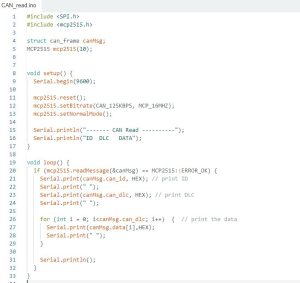
you can download simple example for Read and Write beside the library from this link










Reviews
There are no reviews yet.