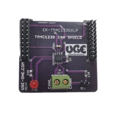
Breaks out essential OBD-II CAN signals
Exposes CAN-H, CAN-L, VBAT, and GND
Clearly labeled signal pads for easy wiring
Compact PCB form factor
Suitable for automotive diagnostics and CAN development
Designed for through-hole header or direct wire soldering
Bare PCB – components and connector not included
Interface Type:
OBD-II (16-pin automotive diagnostic connector footprint)
Exposed Signals:
VBAT (Vehicle Battery Voltage)
CAN-H
CAN-L
GND
Board Type:
Bare PCB (Unassembled)
Signal Access:
Through-hole pads for external wiring or header soldering
Application Level:
Automotive CAN bus development
OBD-based data logging systems
ECU communication testing
Embedded CAN prototyping
VBAT: Direct vehicle battery voltage from OBD connector (typically 12V automotive supply)
No onboard voltage regulation
No CAN transceiver included
Requires external CAN transceiver and microcontroller for operation
Automotive CAN sniffing and monitoring
OBD-II data logger development
ECU diagnostics projects
CAN-based embedded system prototyping
Automotive research and education
1x OBD-II CAN Bus Breakout Bare PCB
Not Included:
OBD-II connector
CAN transceiver
Headers or terminal blocks
Any electronic components
This is a bare PCB only. No components are pre-installed.
Designed for developers familiar with automotive CAN systems.
Ensure proper automotive protection (TVS, filtering, isolation) when connecting to vehicle systems.
Verify OBD pin mapping before assembly.
You must be logged in to post a review.
Reviews
There are no reviews yet.