Description
PCB For WCH-LinkE Programmer
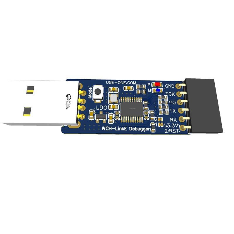
The UGE WCH-LinkE Debugger PCB is a precision-designed printed circuit board intended for building a high-performance WCH-LinkE programmer/debugger compatible with WCH’s RISC-V and ARM microcontrollers, such as the CH32V series and CH32F series.
It allows developers and students to flash firmware, debug applications, and communicate via UART, all from a compact and reliable USB-powered interface.
This version is offered as a bare PCB for DIY assembly, with well-labeled pads and an interactive BOM available for easy soldering.
Product Specifications:
-
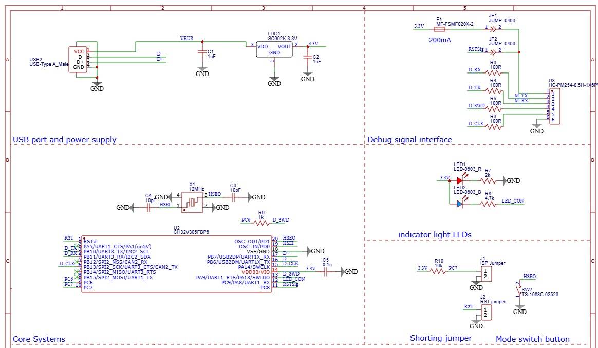
Microcontroller: CH32V305FBP6 (RISC-V4F Core)
-
Supply Voltage: 5V via USB, regulated to 3.3V onboard
-
Voltage Regulator: SC662 Low-Dropout LDO (3.3V, up to 500 mA)
-
Fuse Protection: Resettable PPTC fuse, 0603 size, 200 mA rating
-
Clock Source: 12 MHz SMD Crystal (2.5 × 1.2 mm, ±10 ppm)
-
Load Capacitors: 10 pF precision ceramic capacitors
-
USB Interface: USB Type-C connector (or edge-based USB pads depending on build)
-
Status Indicators:
Pin Configuration:
| Pin Label |
Function Description |
| GND |
Ground |
| TCK |
SWD Clock / JTAG Clock |
| TIO |
SWD Data / JTAG IO |
| TX |
UART Transmit |
| RX |
UART Receive |
| 3.3V |
Target Power Output |
| RST |
Target Reset Line |
Features:
-
Fully compatible with WCH-LinkE firmware for debugging CH32V and CH32F devices
-
Supports both SWD/JTAG and UART programming modes
-
Compact and breadboard-friendly design for lab and development use
-
Includes power and activity LED indicators
-
Built-in current-limiting protection via PPTC fuse
-
High-accuracy 12 MHz oscillator ensures stable communication
-
Designed for easy DIY assembly with labeled components and an interactive BOM
Mechanical Details:
-
PCB Dimensions: 50 mm × 18 mm
-
Mounting: Edge slots for enclosure or USB insertion alignment
-
PCB Finish: Blue solder mask, white silkscreen
-
Silkscreen Labeling: All key components and pins are clearly marked for ease of assembly
- The Soldering Guide manual Diagram
Applications:
-
CH32V and CH32F microcontroller development and debugging
-
RISC-V and ARM Cortex-M firmware programming
-
Educational and DIY embedded projects
-
UART bridge and serial communication testing
Getting Started Guide for WCH-LinkE Debugger (DIY Version)
Based on CH32V305FBP6 – Designed by UGE Electronics
1. Overview
The WCH-LinkE Debugger is a versatile programmer and debugger interface designed for WCH RISC-V and ARM microcontrollers, including the CH32V, CH32F, and CH57x families.
It provides SWD/JTAG and UART communication for programming, debugging, and serial logging.
This DIY version uses the CH32V305FBP6 MCU, SC662 3.3V regulator, and a 12 MHz crystal oscillator for reliable operation. Once assembled and flashed with official WCH-LinkE firmware, it works exactly like the factory WCH-LinkE.
2. Required Components
| Component |
Description |
Quantity |
| CH32V305FBP6 |
32-bit RISC-V MCU |
1 |
| SC662 LDO |
3.3V Voltage Regulator |
1 |
| 12 MHz Crystal |
SMD 2512 ±10 ppm |
1 |
| 10 pF Capacitor |
Load capacitors for crystal |
2 |
| 104 (100 nF) Capacitor |
Decoupling |
2 |
| PPTC Fuse |
0603, 200 mA |
1 |
| Power LED |
Green |
1 |
| Operation LED |
Red or Blue |
1 |
| Resistors |
For LED current limiting (1k typical) |
2 |
| USB Connector |
Type-C or Edge USB Pads |
1 |
| Mode Button |
Tactile push button |
1 |
| Header Pins |
For programming/debug interface |
1 set |
3. Pinout Description
| Pin |
Function |
Description |
| GND |
Ground |
Common ground |
| TCK |
SWD Clock |
Debug clock line |
| TIO |
SWD Data |
Debug data line |
| TX |
UART TX |
Transmit data |
| RX |
UART RX |
Receive data |
| 3.3V |
Power Output |
Power for target circuit |
| RST |
Reset Output |
Reset signal for target MCU |
4. Assembly Instructions
-
Start with small SMD components (resistors, capacitors, crystal, fuse).
-
Solder the SC662 regulator and ensure correct orientation.
-
Mount the CH32V305FBP6 MCU carefully with proper pin alignment.
-
Add the LEDs, Mode button, and USB connector.
-
Finish with header pins for programming and debugging.
-
Clean the board and visually inspect for shorts or solder bridges.
5. Flashing the Firmware
You will need another WCH-LinkE or WCH-LinkW programmer to flash the boot firmware the first time.
Steps:
-
Connect the SWD pins of your existing programmer to the CH32V305FBP6 on your new board.
-
TCK → TCK
-
TIO → TIO
-
GND → GND
-
3.3V → 3.3V
-
Open MounRiver Studio on your PC (download from wch.cn).
-
Import the WCH-LinkE firmware (available in WCH’s official SDK).
-
Flash the firmware into your CH32V305FBP6.
-
Once done, disconnect and power via USB — it should enumerate as WCH-LinkE on your computer.
6. Driver Installation
🔸 Windows:
Linux/Mac:
7. Testing the Connection
-
Open MounRiver Studio.
-
Go to Debug Configurations → WCH-LinkE.
-
Connect a target board (e.g., CH32V103).
-
Click Detect — it should identify the MCU.
-
You can now program or debug your target device.
8. Operating Modes
| Mode |
Description |
| Program/Debug Mode |
Used for SWD/JTAG programming and debugging |
| UART Mode |
Converts USB to UART for serial communication |
| Mode Selection |
Controlled via onboard tactile switch labeled “Mode” |
9. LED Indicators
| LED |
Color |
Function |
| PWR |
Green |
Power ON |
| RUN |
Blue/Red |
Data activity / Debug operation |
10. Applications
-
Debugging CH32V, CH32F, and CH573 MCUs
-
Flash programming for RISC-V and ARM devices
-
USB to UART serial communication
-
Educational and DIY RISC-V development
-
Replacement or clone of factory WCH-LinkE







Reviews
There are no reviews yet.