No products in the cart.





Introduction: IR2104 is a half-bridge gate driver chip . Two IR2104s can be used to build a full-bridge circuit to control the forward and reverse rotation of the motor. However, due to the lack of understanding of the principle, many bugs appeared in the subsequent circuit design. This article serves as an experience summary and a tutorial for novices, explaining the IR2104 circuit design in depth from the working principle of MOSFET transistors.
0. Basic knowledge
IR2104 is a half-bridge gate driver chip (a chip that controls the gate of the MOSFETs that constitutes the half bridge), so before introducing IR2104, let us first understand what MOSFET and half bridges are.
0.1 NMOS principles
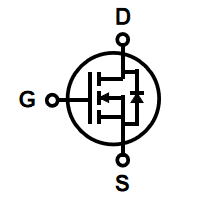
Here is just a brief introduction. NMOS has three pins, namely G (gate), S (source), and D (drain). When there is a potential difference between DS and the voltage between GS is greater than the turn-on voltage Vth, NMOS is fully turned on. The formula is Vgs > Vth.
It can be simply understood as: when the G (gate) voltage is greater than the S (source) voltage, NMOS is turned on.
0.2 Half-bridge control principle
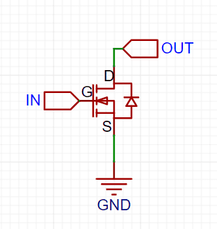
A switch circuit composed of an NMOS (as shown below) can only output a low level or a high impedance state (called an open-drain output), but cannot output a high level.
So we connect another NMOS to control the access of high level (as shown below).
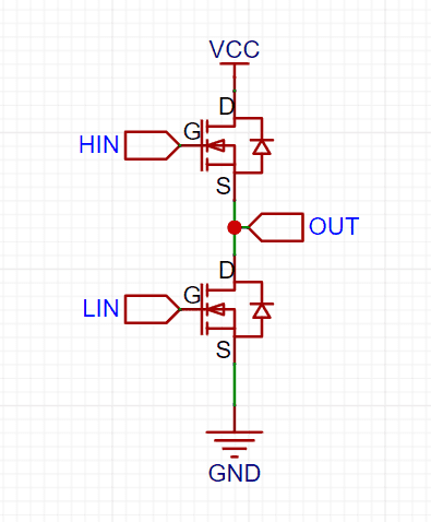
At this time, we call the MOS connected to the high level the upper tube, and the MOS connected to the low level the lower tube. By controlling the conduction of the upper and lower tubes, we can control the output of high and low levels.
When HIN=1, LIN=0, the upper tube is turned on and the lower tube is turned off, and the output is high level;
when HIN=0, LIN=1, the upper tube is turned off and the lower tube is turned on, and the output is low level;
when HIN=0, LIN=0, the upper tube is turned off and the lower tube is turned off, and the output is high impedance;
when HIN=1, LIN=1, both the upper and lower tubes are turned on, short circuit!!!
This circuit seems perfect, but it should be noted that to control the upper tube to conduct, VHIN > Vout is required, and when the upper tube is turned on, Vout ≈ Vcc, that is, VHIN needs to be greater than Vcc to turn on the upper tube. How to obtain a voltage greater than Vcc is the first problem. How to prevent short circuits from occurring during MOS switching is the second problem.
Fortunately, both of the above problems can be solved by using a gate driver chip. Now let’s get to the point – the IR2104 chip.
(Please keep the above two problems in mind)
1. Introduction to IR2104
IR2104 is a high voltage, high current, half-bridge driver for driving power MOSFET and IGBT. It integrates dead zone control circuit and shutdown function.
1.1 Example Circuit

1.2 Pin Definition
| Serial number | Pin Abbreviation | Description | Pin Function |
|---|---|---|---|
| 2 | IN | Logic input for gate driver outputs (HO and LO), in phase with HO | Logic input, controls the output of HO and LO pins, in phase with HO |
| 3 | SD# | Logic input for shutdown | Logic input, low level chip stops working |
| 8 | Vb | High side floating supply | High-side floating power supply |
| 7 | HO | High side gate drive output | High-side gate drive output |
| 6 | Vs | High side floating supply return | High-side floating power supply return |
| 1 | Vcc | Low side and logic fixed supply | Low-end fixed power supply, logic circuit power supply |
| 5 | LO | Low side gate drive output | Low-side gate drive output |
| 4 | COM | Low side return | Low-side return, common ground |
Pins can be divided into two categories
- Logic pins
- The IN pin controls the output of the gate drive pins HO and LO, and the HO level is the same as IN, and the LO level is opposite to IN.
- The SD# pin controls whether the chip works or not. “#” means low level is valid, that is, the chip stops working when SD is low level.
- Drive pin
- VB/HO/VS can be regarded as a group of driving pins to drive the high-end NMOS
- Vcc/LO/COM is a set of drive pins that drive the low-side NMOS
In the Engineering definition of pins, the words floating and fixed appear, meaning “floating” and “fixed”, respectively describing the high-end and low-end drive pins.
Point them out here and explain them later.
2. Detailed explanation of circuit principle
Remember the two key questions at the beginning? Let’s review them.
- The first question: How to obtain a voltage greater than Vcc
- The second question: How to prevent short circuits?
The solutions to these two problems correspond to two new terms—bootstrap voltage boost and dead zone control.
Before learning them, let’s make a diagram to analyze the working process of the internal and external circuits of the chip (as shown below)

2.1. Bootstrap
Bootstrapping, as the name suggests, means lifting oneself up, which is mainly achieved through a capacitor and a diode. Let’s do a small experiment. Now there is a 5V power supply and an electrolytic capacitor. Connect the power supply and the capacitor in parallel. At this time, the capacitor is charged and the voltage across the two ends is equal to 5V. Remove the capacitor, connect the negative pole of the capacitor to the positive pole of the power supply, and measure the voltage between the negative pole of the power supply and the positive pole of the capacitor. You can see that the measurement result is 10V.
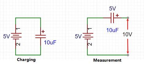
This is the meaning of bootstrapping, which is to first gather one’s own energy into the capacitor, and then superimpose the energy to increase the voltage.
Let’s take a look at the actual working process of the bootstrap circuit. (Note: the output of HO and LO is also controlled by the internal MOS)
When the input of IN is 0, LO and Vcc are connected, the lower tube is turned on; HO and VS are connected, and the upper tube is turned off. At the same time, the current is charged from Vcc to the bootstrap capacitor through the diode.
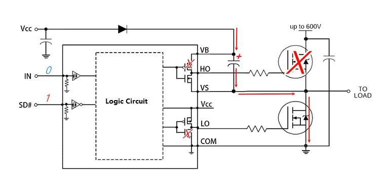
When IN input is 1, LO and COM are turned on, and the lower tube is turned off; HO and VB are turned on. At this time, the positive electrode of the bootstrap capacitor is equivalent to connecting HO, and the positive electrode voltage of the capacitor = Vbat + Vcc. At the same time, the diode prevents the current from flowing back to Vcc, and the upper tube is turned on.
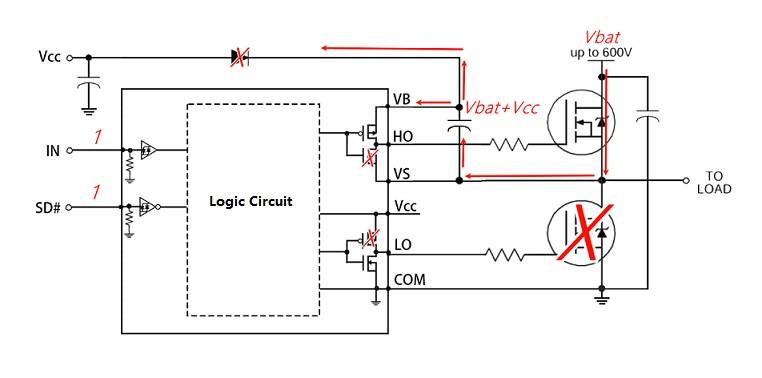
But this is not a one-time solution ( charge once, conduction for life ). The capacitance of the bootstrap capacitor depends on the control frequency of the circuit and the gate-source capacitance of the NMOS, so it will not be very large. There will be some leakage when driving the MOS, so the above process needs to be repeated to charge and discharge the capacitor in order to maintain the on-voltage of the MOS.
Let’s do another experiment. Take an IR2104 module and input a high level to IN after power-on. You will find that the output of the upper tube can only be maintained for a short period of time. It is necessary to input a low level to IN and then give a high level again to restore the conduction of the upper tube.
The two English words above (floating, fixed) can be explained here.
- Floating means floating, which vividly describes the driving power supply of the upper tube. The bootstrap capacitor is like a small boat. Its positive voltage rises with the Vbat and is erratic, indicating uncertainty.
- Fixed means fixed, which is easy to understand when compared with floating. The driving power supply of the lower tube is Vcc, which is fixed.
2.2 Dead zone control
Dead zone, as the name suggests, is a “dead zone”.
In order to prevent the upper and lower MOS from being turned on at the same time during the control process, a “dead zone” is added to the control output signal inside the chip, that is, the interval where both MOS are not turned on.
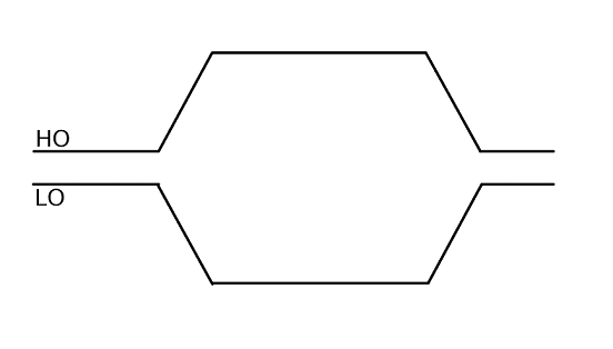
The waveform without adding dead zone looks like this
The waveform with dead zone added looks like this
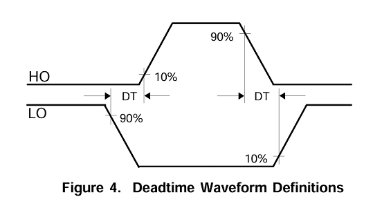
It can be seen that when there is no dead zone, when the half-bridge switches the output state, the upper and lower tubes will be in an incomplete conduction state at the same time. This phenomenon may cause output instability and increase power consumption at the least, or cause the MOS to heat up or even short-circuit and burn out at the worst.
After adding the dead zone, when the half-bridge switches the output state, it will first ensure that both the upper and lower tubes are in the cut-off state before switching.
Combined with the data table below, we can see that the value of DT is between 400~650ns. This parameter can be used as the basis for MOS selection.
The internal capacitance of a MOS tube refers to the capacitance between the channel and the gate, while the external capacitance refers to the capacitance between the channel and the external environment. These two capacitances will affect the charge transfer speed during the switching process, thereby affecting the dead time. Generally speaking, larger internal and external capacitances will lead to longer dead time, while smaller internal and external capacitances will shorten the dead time. Therefore, when designing MOS tube circuits, we should try to reduce the size of internal and external capacitances to reduce the dead time.

3. Summary
OK, now you have mastered the key knowledge points of IR2104. Let’s sort it out.
- First of all, IR2104 is a half-bridge driver chip, and the half-bridge is composed of two NMOS, so we first understand the conduction conditions of NMOS and the control principle of the half-bridge. However, the control process encountered two problems, the high voltage required for the upper tube to turn on and the short circuit prevention of the control process.
- Later, based on these two problems, we found the corresponding solutions on IR2104, bootstrap boost and dead zone control, and understood the reasons and necessity of using gate drive chips.
- Finally, there are actually many issues that have not been explained in depth in this article, such as the capacitance of the bootstrap capacitor, the resistance of the current limiting resistor, and how to build a reliable motor drive circuit. These will be in the next article (wait for me).